Get Started midas Civil
 Featured blog of this week

Common Errors in Bridge Modeling
Table of Contents
1. Finite Element Modeling of Bridges
2. Common Errors and Discussion
3. Recommendations
1. Finite Element Modeling of Bridges
Finite element theory is not exclusive to the area of bridges, but there are tendencies to use certain techniques and types of finite elements in this area of structural engineering. Usually, in bridge modeling, finite element capabilities of an intermediate level of complexity are used, encompassing modeling with elements like joints (nodes), lines (frames, trusses, cables, etc.), surfaces (plates, membranes, etc.), and volumes (solids), being the firsts more frequently used than the latter. Although linear models are also frequent, on many occasions basic non-linear characteristics are used, for example:
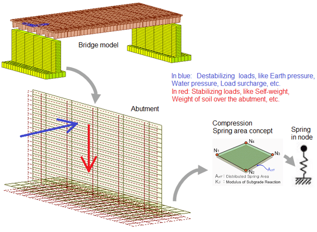
Compression-only springs, to represent ground support
This type of nonlinearity usually requires a special modeling configuration for the load cases because destabilizing loads can lead to non-convergence of the solution of the model. Then, stabilizing and destabilizing loads should be combined before the analysis, if performed.
Time-dependent properties of materials
In concrete, time-dependent properties are used to capture the effects of plastic flow, shrinkage, and modulus of elasticity. In high-strength steel for prestressed bridges, they are used to reflect the relaxation of the steel.
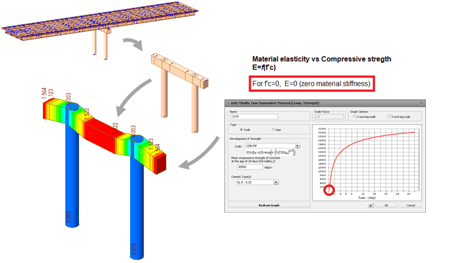
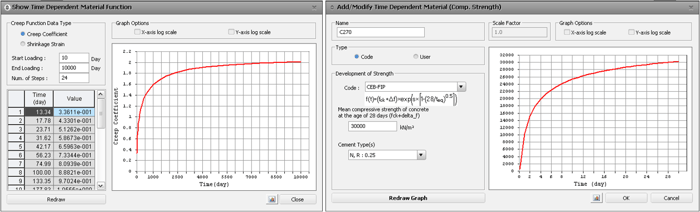 Figure 2. Time-dependent variables of concrete: creep and shrinkage (left) and compressive strength (right)
This type of nonlinearity does not require a combination of stabilizing and destabilizing loads for the analysis, but other considerations like time step size and concrete age take importance.
Other Concepts
- Analysis by construction stages, which are essentially non-linear analyzes since the stiffness of the structure changes from stage to stage.
- Geometric non-linearity, especially to analyze very flexible bridges such as those supported by cables, both due to the deformations of the structure in general and the great non-linearity of the cables themselves.
Features like the last one may not be basic, but programs such as midas Civil, focused on bridges, make it easier to perform this type of analysis by having features and functions that allow them to configure and streamline the representation in the numerical model.
In bridges, other special modeling concepts are important:
- Special boundary conditions to represent connections between elements.
- Meshing and analysis configurations specifically designed for moving loads.
- Releases of the degrees of freedom explicitly or implicitly for the expected real behavior of certain structural members such as braces or stiffeners.
2. Common Errors and Discussion
The following are some frequent errors and mistakes made in finite element modeling of bridges:
- Supports of the superstructures
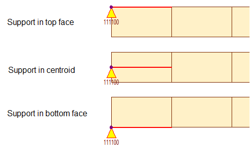 Figure 3. Different locations of beam for a simple pin support
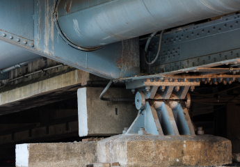
Unlike buildings, many structural members of bridges do not rest on the centroid of other elements but on the lower faces. This is the case of most superstructures, for example, beams bearing in reinforced elastomers, and these, in turn, transmit the loads towards the substructure.
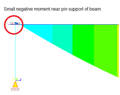
An effect of the support at points other than the centroid is the small moment generated by the eccentricity of the reaction. The beam needs to rotate in the support, but the eccentricity of the actual support in the bottom face of the girder produces a horizontal force, which in turn, produces a reaction moment in the girder, so it is not uncommon to see small negative moments even when the superstructure corresponds to a simple pin support:
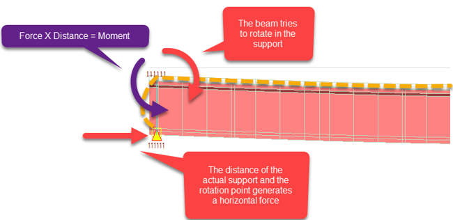 Figure 4. Free body diagram of the rotation of a beam with elastomeric bearings
It is a common mistake to think that these small negative moments should not exist and to look for ways to eliminate them when it really is something that is expected according to the reasons given.
When the design verification is to be performed in the program, for example in midas Civil, the elements with the small negative moment will be verified for negative flexure. Sometimes, however, no negative flexural reinforcement is assigned because no negative moment was expected, so the program will indicate that this reinforcement is required. The engineer has two options:
1. Disregard the message under the fact that the negative moment is very small, close to zero.
2. Include some negative moment reinforcement that will usually correspond to the shrinkage and temperature reinforcement in the top face of the girder. This will provide enough flexural strength, usually much more than that required in this context.
One additional variable that can increase the magnitude of the negative moment is the stiffness of the elastomeric bearing when this type of element is used. When compared to the connected elements in the model, the stiffness of the elastomeric bearing is small, and so will be the negative moment. For more information about how to calculate the elastomeric bearings stiffnesses and modeling considerations, read the article Elastomeric Bearings for Bridges: Stiffness and Tips for Modeling
- Lack of convergence when using nonlinear capabilities like compression-only spring supports
This case was already presented in the first chapter. If stabilizing and destabilizing loads are not combined, the finite element program will probably indicate a lack of convergence:
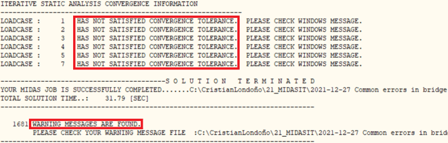
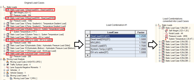
In those cases, the engineer should remember that the programs usually don’t solve the equilibrium equations for the Load Combinations but for the Load Cases (in the case of midas Civil). Thus, the equilibrium can be achieved only if the stabilizing and destabilizing loads are being simultaneously considered in each Load Case. In other words, the Load Combinations need to be input as Load Cases. If the equilibrium cannot yet be achieved, it would probably mean that the real structure has stability issues (most likely the destabilizing effects cannot be counteracted by the stabilizing loads).
- Lack of convergence when using finite elements with releases of degrees of freedom
It is always tricky to use elements with released degrees of freedom, either explicitly or implicitly. It is made explicit when, for example, a beam element has the rotational stiffness at the ends deactivated. It is implicit when instead of doing the above, a finite axial element (truss) is used.
On many occasions, the analysis does not converge because many degrees of freedom have been released so the model is not stable during the analysis. In this case, it is sufficient to make a simple analysis of the load trajectories and make sure that, for any of the finite elements or the overall model, the structure is stable.
- Lack of convergence when analyzing bridges by construction stages
If the model considers the modulus of elasticity of the concrete that is variable over time, it must be guaranteed that all parts of the structure are activated with a modulus of elasticity higher than zero. Otherwise, this will result in null stiffness, and therefore convergence problems. This can be easily detected by observing the deformations of the structure in each construction stage or by trying to activate and deactivate the variable properties to assess. In that case, the problem is most likely solved by setting the element being activated with a concrete maturity (age) greater than zero.
Most times, the bridge engineer defines the time step sizes of the construction stage according to the main stages of the construction, for example, beam casting and placing, slab casting and placing, etc. But it is always important to ensure adequate time step sizes when time-dependent materials are used. In the following graph, the highlighted part of the curve could be wrongfully taken with the poor time step size indicated:
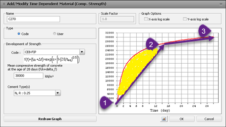 Figure 10. Poor time step for the analysis of time-dependent materials.
In midas Civil, this is not usually a problem because there are internal rules for considering smaller time steps when time-dependent materials are used.
If the convergence difficulties in a model that uses construction stages are not due to the properties of the concrete, it must be ensured that the supports of the structure are being activated at the correct times.
For the validation, many times a quick visualization of all the stages is sufficient, observing the supports that are activated. It would be easy to detect that some support is needed in the structure. It also helps to observe the error messages of the program to detect the exact construction stage where the problem occurs, as allowed by midas Civil.
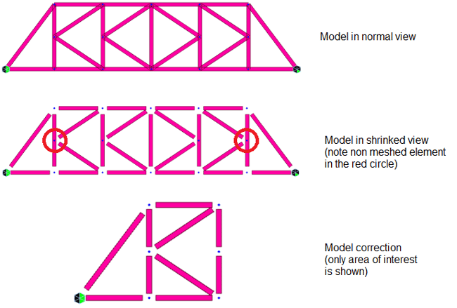
- Parts of the structure are disconnected in deformed view but not in normal view
If a model shows that the structure is disconnected only when the deformation results are observed, it is most likely that the corresponding finite elements are not really connected.
On many occasions when DXF files with the base geometry of the structure have been imported, it is likely that the structure is apparently connected, but a drawing error has produced two very close but separated nodes. It is difficult to detect this in an undeformed view of the structure due to the proximity of these nodes, but it is enough to merge the nodes with tools such as Civil midas merge.
This error can also occur when the mesh of the structure has been done manually and it ignores splitting existing elements in the location of the new nodes included. In this case, simply use tools such as shrink, where you can see how the finite elements and nodes are connected thanks to the shrinkage of the edges. If the program does not shrink the elements in a specific node, it is probably necessary to intersect (intersect) the finite element in that position.
3. Recommendations
In addition to the recommendations given above to solve these frequent errors, you can also follow some general guidelines to avoid errors or to solve them quickly:
1. Start with simple models and gradually increase the complexity as necessary
2. As much as possible, the models should be tested as new things are implemented. It is not good to wait to have the whole model implemented because the sources of errors can increase.
3. Follow the example of modeling similar cases, such as those shown in the midas Civil webinars, but always use good engineering judgment to ensure applicability in each case.


.png)