Get Started midas Civil
 Featured blog of this week

Please fill out the Download Section (Click here) below the Comment Section to download the The Complete Guide to Temperature Gradient
Finalizing the Forces in the Cables for a Cable-Stayed Bridge
Table of Contents
1. Introduction
2. Unknown Load Factor Method in midas Civil
3. Main Factors to be Considered for Cable Optimization
1. Introduction
A cable-stayed bridge is the most popular long-span bridge in which cables support the bridge deck and transfer the load to one or more towers(or pylons). Mostly the cables form a fan-like pattern or series of parallel lines. The main span of cable-stayed bridges, which consists of two towers, ranges from 100m to 1100m. Analysis of cable-stayed bridge involves two main stages:
1.1 Final Stage Analysis
Starting Point of a cable-stayed bridge is an idealized stressed state at a given time for permanent loads, and this is called the final stage. Initial cable forces are determined for this final stage. Further static and dynamic analyses are undertaken using the final stage.
1.2 Construction Stage Analysis
Construction stage analysis of a cable-stayed bridge can be in backward sequence or forward sequence. As the determination of the initial cable forces of the final structure does not consider the actual construction process, a detailed construction stage analysis is needed to determine the forces in the cables at each construction stage. Further, we check stresses in the girder, pylon, and cables at each construction stage such that cable forces of each stage are finalized.
2. Unknown Load Factor Method to Optimize Cable Pretensions
In the design of cable-stayed bridges, we often face a problem where we would seek a solution to cable forces necessary to satisfy a given design requirement. Midas Civil can solve this type of problem using an optimization technique by calculating the optimum variables for given constraints and object functions. For constraint conditions, equality and inequality conditions are permitted.
By using the optimization technique, a solution satisfying the equality/inequality conditions is obtained. Numerous solutions to the unknown loads exist depending on the constraints imposed on the Equality/Inequality conditions. Midas Civil finds a solution to Equality/inequality conditions, which uses variables that minimize the given object functions. Midas Civil allows us to select the sum of the absolute values, the sum of the squares, and the maximum absolute values of variables for the object functions. Weight factors can be assigned to specific variables to control their relative importance, and the effective ranges of the variables can be specified.
A comprehensive understanding of a cable structure is required to use the above optimization technique for finding necessary design variables. Since Equality or Inequality conditions may not have a solution depending on the constraints, selecting appropriate design conditions and object functions is very important.
Unknown Load Factor Method can be used for:
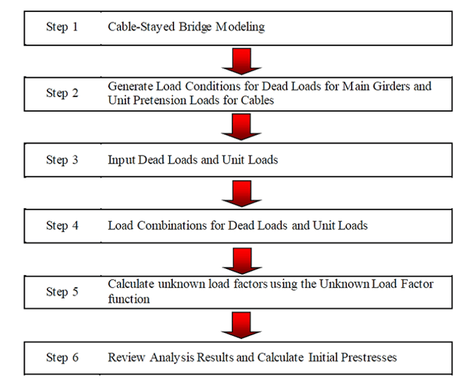
The procedure of calculating the initial prestress for the cable-stayed bridge by the unknown factor method is outlined in Figure 1.
Cable stayed bridges are generally considered to be a reliable and safe type of bridge structure. However, in rare cases, cable stayed bridge collapse can occur due to various factors such as design flaws, construction defects, and natural disasters. One notable example is the collapse of the Tacoma Narrows Bridge in Washington State in 1940, which was caused by aeroelastic flutter due to high winds.
To ensure the safety and reliability of cable stayed bridges, engineers use various analysis techniques to assess their structural integrity. One such technique is the static analysis of cable-stayed bridges, which involves determining the forces acting on the bridge structure and analyzing its response to static loads.
Another important aspect of cable stayed bridge analysis is the transverse analysis of PSC box girder bridges or box girder bridges. This involves analyzing the bridge's resistance to lateral forces, such as wind or earthquakes, which can cause the bridge to sway or vibrate.
One example of a cable-stayed bridge that has undergone extensive analysis is the Octavio Frias de Oliveira Bridge in São Paulo, Brazil. This cable-stayed bridge spans the Pinheiros River and has a unique curved design. Engineers used static and transverse analysis techniques to ensure the bridge's stability and safety.
3. Main Factors to be Considered for Cable Optimization
3.1 Creep and Shrinkage Properties
3.2 Multiple Tensioning of Cables
3.3 Large Displacement Effect
3.4 Constraints to be Given Based on Real Displacements
3.1 Creep and Shrinkage Properties
Creep and shrinkage effects will be significant in long-span bridges like cable-stayed bridges. Optimized pretension without considering the erection sequence can be obtained using an unknown load factor method and further these pretensions shall be used for creep and shrinkage.
3.2 Multiple Tensioning of Cables
As Unknown Load Factor does not support multiple tensioning in finding the cable forces, we have to assign the first tensioning as “Unknown” and then optimize the cable forces.
3.3 Large Displacement Effect
Large displacement effects can be significant, and there can be convergence issues if the large displacement effect and creep&shrinkage effects are considered simultaneously in the first run of the unknown load factor method. Hence it is recommended to optimize the cable pretension first by considering creep and shrinkage only. Then in the next step, a large displacement effect (Non-linear construction stage analysis) can be considered with these pretensions.
3.4 Constraints to be Given Based on Real Displacements
If the real displacement of the deck needs to be considered in the unknown load factor method, then we can create a dummy deck element line along the main span, which will share the common node with actual deck elements. These dummy deck elements shall be activated before the actual main deck elements are activated in the beginning stage. This approach will consider the tangent displacement of the deck.