 Get Started midas Civil
 Featured blog of this week

Network Tied Arch Bridges
Table of Contents
1. Introduction
2. Efficiency of Network Arches
3. Case Study: Comparison of Network Tied Arch Bridge with Conventional Tied Arch Bridge
4. Conclusion
1. Introduction
Network tied arches are tied arch bridges with inclined hangers where hangers intersect other hangers at least twice. Network tied arch as a concept was developed by Dr. Per Tveit. The world’s most slender arch bridge, The Brandanger Bridge, situated in the western part of Norway, was designed by Dr. Per Tveit and was opened in 2010 (Fig 1). Before this, bridges with inclined hangers were made popular by Nielsen – Lohse (Fig 2). However, these bridges had a drawback in the case of dynamic loads. Under dynamic load, the tension in inclined hangers is reduced, leading to compression in some hangers. The network tied arch developed by Dr. Tveit with multiple crossing of hangers avoided this issue.
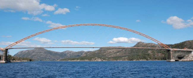 Figure 1. The Brandanger network arch bridge (span 220m) in western Norway.
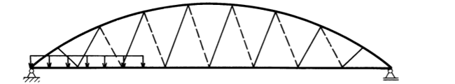 Figure 2. Arch bridge with inclined hangers. One-sided load makes the dotted hangers relaxed.
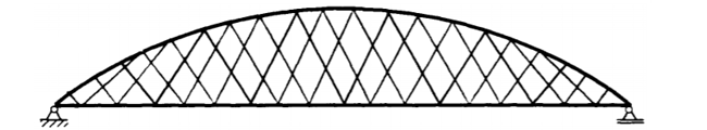
The compression in the hangers can be avoided by increasing the distance between the nodal points. However, increasing the distance will increase the bending moment in the chords, thus reducing the buckling capacity of the arch. Between the hangers, the arch tends to move up, and the tie tends to move down. An extra set of hangers will reduce the buckling length in the arch and tie, resulting in less bending in the arch. This effect is even more significant if we put three sets of hangers (Fig 3). We arrive at network tied arch geometry with some of the hangers intersecting at least two other hangers with this arrangement.
2. Efficiency of Network Arches
In contrast to conventional tied arch bridges, in network tied arch bridges, the arch and tie beams are mainly subjected to axial load and less longitudinal bending, leading to considerable steel saving. As a result, longitudinal bending does not govern the network arch design. As shown in later comparison as well, this results in more efficient use of material (lower steel weight) and more slender arch cross-sections. For network arch bridges, transverse bending is more than longitudinal bending, causing the transverse load to determine the design of concrete or steel composite tie members. Furthermore, wind bracings transversely stiffen the arches.
The network arch is analogous to a simply supported beam with chords as tensile and compressive flanges and hangers as webs. Most of the shear force is transferred to support the vertical component of forces in the arch. Much of the variation in shear force is taken by variation in hanger force. The hanger distributes the forces to the chords, leading to very little bending and predominantly axial load. The stiffness of the network arch bridge is hugely affected by hanger arrangement. Hanger arrangement includes the number, position, and inclination of the hangers. This has considerable influence on the distribution of internal forces. Usually, hangers are placed with equal spacing along the upper chord, resulting in a simplified construction process, uniform buckling length, and a smaller bending moment along the arch. A few of the common hanger configurations are mentioned below:
Constant Slope Configuration: This is the most common method of network hanger arrangement. In Japan, almost every network arch bridge has this arrangement.
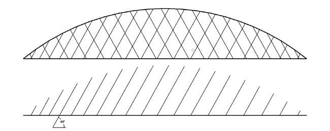 Figure 4. Constant slope of hangers
Variable Slope Configuration: In this case, the slope of the hanger varies following a function. A general case is illustrated below.
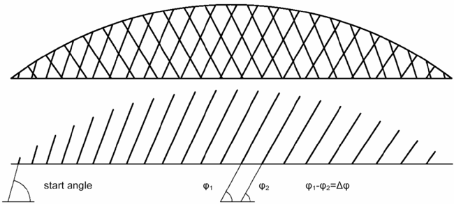 Figure 5. Variable slope configuration
Advanced Hanger Configuration: When subjected to UDL, the forces in the hanger are minimized when they are in a radial direction like in a ‘spoked wheel.’ Below shown (Fig 6) is a modified version of the ‘spoked wheel’ model. For such arrangements, if forces in each hanger are approximately equal, the resulting forces will lie on the radii of the arch circle.
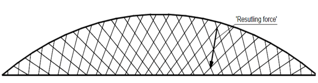 Figure 6. Advanced hanger configuration
3. Case Study:
Comparison of Network Tied Arch Bridge with Conventional Tied Arch Bridge
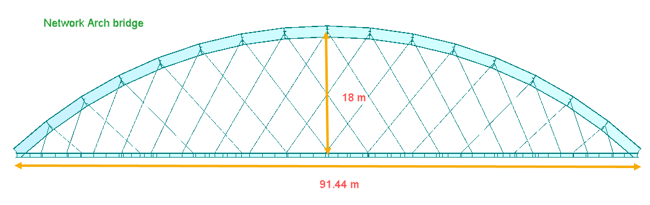
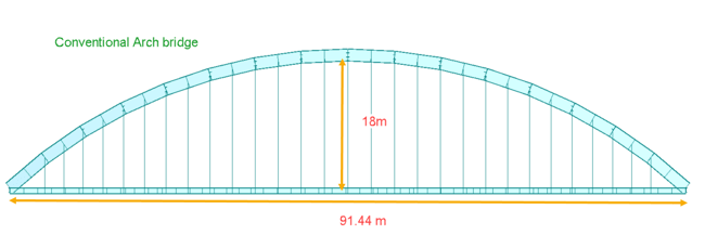
This case study will look at the forces, moments, and deformation in arch and tie beams of network and conventional arch bridges under static and live load. The bridge configuration considered for the case study is shown in fig 7. A similar configuration of the bridge is considered for both cases. Span considered is 91.44 m (300 ft), and the arch rise considered is 18m. All the arch, tie, crossbeams, and cables sections are kept the same for both cases.
For live loads, a single lane of LM 71, rail traffic load as per Eurocode is considered on the bridge.
In conventional arch bridges, all the hangers are vertical, and they are less in number than the network arch bridge. But for the sake of comparison, we will consider the same number of hangers for both configurations. The results of the following two cases will be checked:
- LC 1: Self-weight and SIDL
- LC 2: Self-weight, SIDL, and Live Loads
The decisive force for an arch bridge is axial load and bending moment (in arch and tie). Axial load is the function of the span of the bridge and arch rise. As they are the same for both the bridges, axial loads are also similar. However, the longitudinal moment shows the critical difference in the load-carrying pattern of both the bridges.
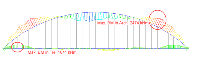
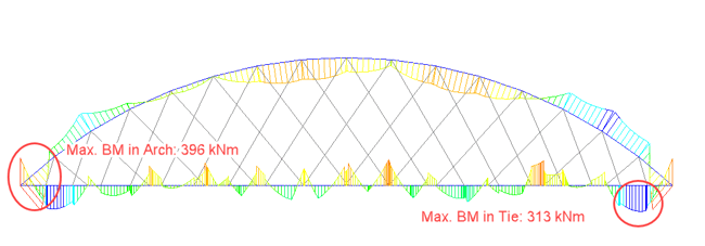
Fig 8 compares the bending moment in the arch and tie due to the LC1 (self-weight and SIDL). A uniform loading is considered throughout the span. The load is predominantly transferred to the arches through the hangers for conventional arch bridges, causing bending moments in the arches. On the other hand, there is no significant bending moment in arches and ties in the case of network arch bridges. For LC 1, the bending moment ratio between the network arch and the conventional arch is 1:6 for arch and 1:3 for tie beams.
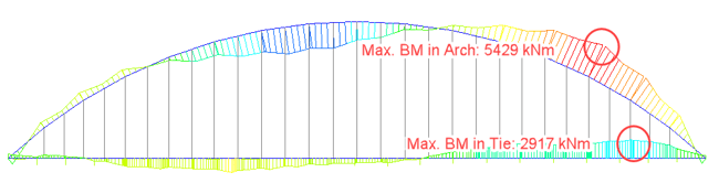
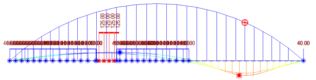
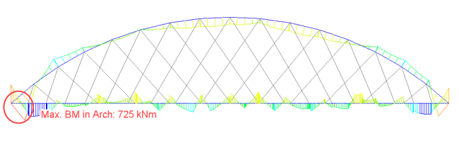
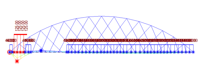
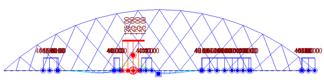
For LC 2, LM 71 live load vehicle on a single track is considered. Fig. 9 and 10 show the maximum bending moment in tie and arch due to LC 2 and the critical position of the vehicle causing this bending moment for both types of arch bridges. Like LC 1 case, the load is predominantly carried by arches and tie beams for conventional arch bridges. However, in the case of network arch bridges, the load sharing is even, and the cross girders connecting the tie beams carry a significant amount of load. Therefore, network arch bridge decks are designed for transverse bending rather than longitudinal bending. For LC 2, the bending moment ratio between the network arch and the conventional arch is 1:7.5 for arch and 1:4 for tie beams.

4. Conclusion
Clearly, the above comparison shows that network arch bridges are more efficient than conventional arch bridges. Network arches are stiffer structures due to higher redundancy, and inclined hangers result in better moment and shear distribution in the structure. This can lead to slender arch sections and slimmer tie beams, leading to up to 45% savings in material cost compared to conventional bridges. Network arches are not sensitive to uneven settlements as well. High strength and low weight make network arch bridges dynamically robust structures. Hence network tied arch bridges are clearly a better choice as compared to conventional arch bridges.


/2020%20Pics%20for%20drafts/Moving%20Load%20All%20You%20Need%20to%20Know-1.jpeg)
/MC%2004%20Section/How%20to%20Define%20Section%20Properties%20in%20Various%20Bridge%20Design%20Conditions%20345%20240.png)
/345%20240/Application%20of%20Links%20in%20Bridge%20FE%20Models.png)