Get Started midas Civil
 Featured blog of this week

Spine and Wind Construction
Table of Contents
1. Introduction
2. Structural Elements of Spine and Wing
3. Modeling
-
Single Line Longitudinal Modeling
-
Transverse Modeling
4. Conclusion
1. Introduction
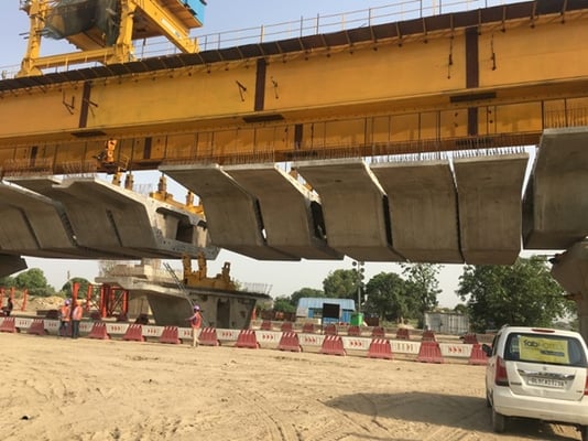
In modern-day cities, the availability of space for carrying out construction activities as well as sparing space for infrastructure is becoming difficult day by day. There is a growing demand for more urban space and innovative transportation planning and development to meet that demand. Often, there is a restriction of the available width. The current trend in urban areas is to go for elevated roads which can avoid costly land acquisition, decrease traffic congestion and improve the speed of movement. However; the construction of long elevated corridors has a few challenges of its own. Usually, they require twin/multiple piers, covering a major part of the space underneath the superstructure. With the use of pre-casting and segmental technology for fast-track solutions, the trend is now shifting to the provision of only a single median pier to cover the entire deck, which also renders the space underneath the deck to be used for traffic movement as well. One such technology is the spine and wing construction technology.
2. Structural Elements of Spine and Wing
Spine and wing basically contain 3 components: single/multicell box girder over the pier, wide central spine, and 2 equal wings hanging from either end of the box girder. Furthermore, these are generally accompanied by rib construction which connects the central spine with the wing. Generally, the central spine and wings are pre-casted separately. These pre-casted segments are stitched together with the help of transverse prestressing. So, all in all, spine and wing bridges are accompanied by both longitudinal as well as transverse prestressing.
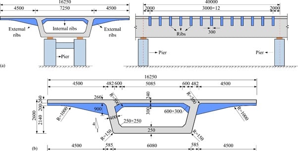 Figure 2. General configuration of spine and wing bridges
This type of nonlinearity does not require a combination of stabilizing and destabilizing loads for the analysis, but other considerations like time step size and concrete age take importance.
General Construction Process
Firstly, precast spine segments are launched and stitched together to each other using epoxy and temporary prestressing. Once all the segments are placed, permanent longitudinal prestressing is done and they are placed over the bearing. Subsequentially, cantilevered wings are stitched transversely to the spine along with ribs. This stitching is accompanied by transverse prestressing. This completes the general construction of the superstructure.
3. Modeling
Generally, three types of modeling methodologies can be adopted for numerical modeling and analysis of bridges. A) Longitudinal Modeling B) Transverse Modeling.
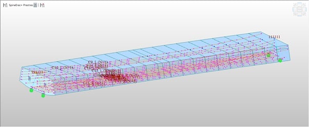
A) Single Line Longitudinal Modeling
In single-line longitudinal modeling, the properties of the entire cross-section are defined for the elements and Line Modelling is used to generate the geometry of the bridge.
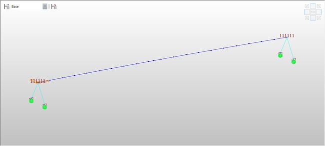 Figure 3. Line model
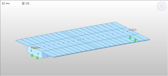 Figure 3. Line model
The major benefit is that analysis is very quick and longitudinal design could be performed with this model. It should be noted that in such a type of modeling, we cannot get any results in the transverse direction from the analysis in the global system. Only the longitudinal results like the bending moment, shear force, torsion, stress variation, etc. along the longitudinal direction can be obtained.
B) Transverse Modeling
In a transverse model, the cross-section is subdivided into smaller elements and the transverse behavior for the required location can be modeled and analyzed. For wide structures like this, it is recommended to model at least 1 span. It is generally advised to create both types of models to get a complete understanding of the structural behavior.
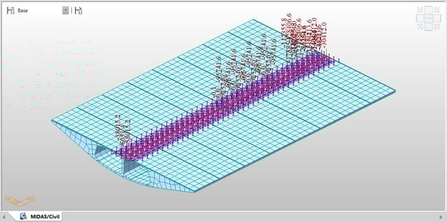 Figure 5. Transverse Model
Now with this background about the modeling methodologies, we shall now discuss the modeling of a Spine and Wing Construction Method.
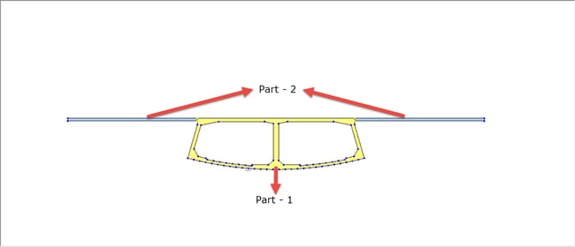
For modelling Spine and Wing type bridges, the longitudinal and transverse modelling methodology is used in this article. The cross-section can be modelled as a composite section with Spine being Part-1 and the Wings as Part-2. This type of section can be defined using Section Property Calculator in midas.
The Construction sequence of the bridge is as discussed below.
- Stage 1: Erection of substructure
- Stage 2: Precast Spine segment erection with overhead Launching Girders and Suspenders
In the first stage, the precast spine segments are erected with the help of Launching Girders; then Spine Beams are placed on the Temporary Bearings, and initial longitudinal Prestressing is applied.
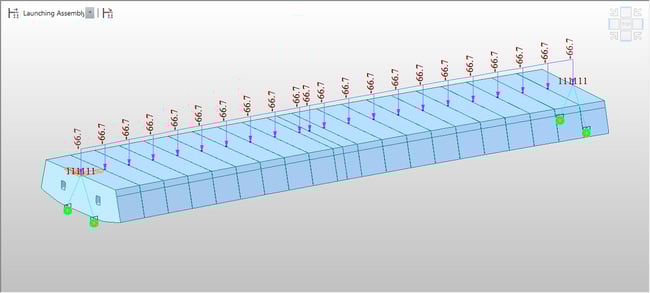
- Stage 3: Launching Assembly
The launching assembly loads are now applied to the spine sections.
- Stage 4: Wings Lifting
The Precast Cantilever Wings are now lifted and placed in position so that the connections can be made to the erected spine. In this stage, the stiffness of wings would not contribute to the overall stiffness and the weight of wings need to be resisted by the Spine itself.
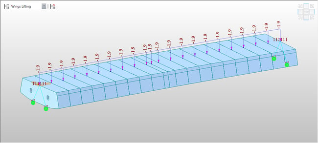 Figure 10. Construction stage 4
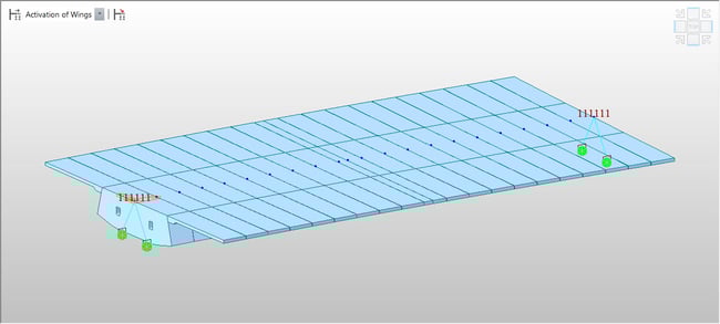
- Stage 5: Wings Activation
In this stage, the cantilever wings are now connected to the erected Spine with Stitch (Cast In-situ) and prestress is applied to the wings also. However, from the modeling point of view, the transverse prestressing will need to be done analyzed in Transverse models. The stiffness of the entire cross-section now resists the loads.
- Stage 6: Removing of Launching Girders
The Launching Girders are now removed and placed for the construction of the next span. In the model, the removal of loads takes place in this stage.
- Stage 7: Activation of Superimposed Dead Loads and Crash Barrier Loads
The crash barrier and wearing course can now be placed on the span using elemental beam loads.
- Stage 8: Long Term Effects
For studying the Long Term effects of the prestressing, the final stage is defined with a duration of about 10,000 days (or as per the user’s requirement).
The Moving Loads can now be defined with the required traffic lanes and vehicle definitions. The most critical load combinations can then be extracted and applied in the transverse models.
Transverse Modeling
The Transverse model is created by importing the section geometry into Midas and extruding the elements to create plate elements. For defining the prestress tendon profiles, dummy members (beam elements) are used across the section.

For defining the moving loads, traffic surface lanes are used and the most critical output for Dead Loads and Live Loads combined in a particular section can be analyzed. Vehicle position is obtained from the longitudinal model and can be applied as pressure load or the complete span can also be modeled along with the moving load analysis.
4. Conclusion
The difference of output amongst the two methodologies can be observed from the deformation contours below:
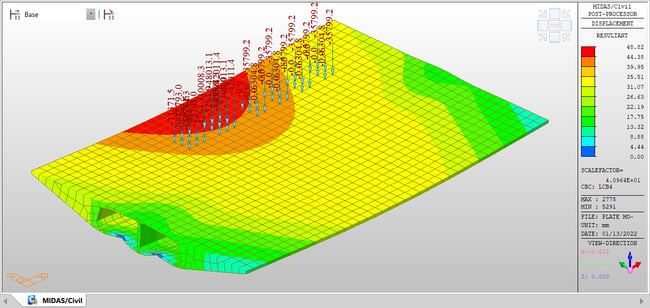
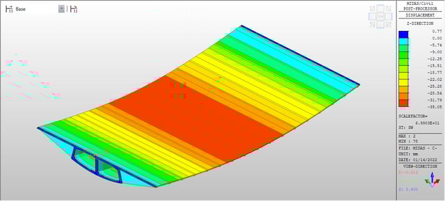
It can be observed that in the transverse model, the deformation profile at various locations can be studied but in the longitudinal model, the entire cross-section behaves rigidly and deforms together. On the other hand, it is easier to perm design in the longitudinal models as compared to transverse models. Thus, the modeling depends on the requirements.
References
- Heggade, V N. (2021). CONSTRUCTION-CENTRIC SUSTAINABILITY OF PRECAST EGMENTAL BRIDGES CONSTRUCTED WITH SPAN-BY SPAN METHOD.
- Christopher D. White and John E. Breen. Evaluation Of The Composite Wing Girder Bridge At Bear Creek


.png)