 Get Started midas Civil
 Featured blog of this week

Super T-Girder Bridge Design as per AS 5100
Please fill out the Download Section (Click here) below the Comment Section to download the Full Webinar PDF File
Super T girder bridges are the most widely used bridge type in Australia for spans ranging from 18m to 35m and can be used for straight and highly skewed bridges. Various advantages like good torsional resistance, flexibility in changing flange widths, and aesthetically appealing shape make the Super T girder bridges an excellent choice in the bridge industry.
This webinar will cover the various modeling and design aspects of Super-T girder bridges as per AS 5100 using midas Civil software.
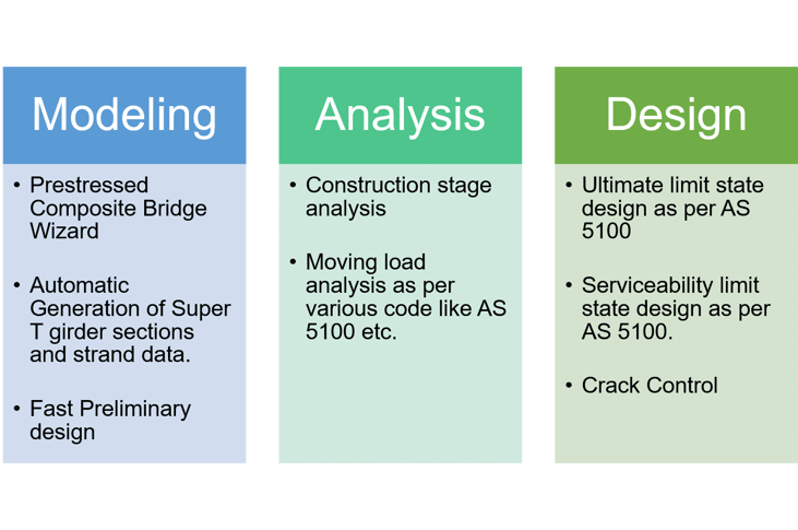
Key Points
Key point 1: Introduction to Super T-Girder Bridges
Super T girder bridge is a common choice among the designers for medium span bridges. Super Tee section is a precast and prestressed section with open or closed flange.
Key point 2: Modeling Methods of Super T Bridges
We will be learning about various modeling methodologies that can be used to model Super T bridges in midas Civil. We shall see how quickly a model can be developed using midas Civil PSC Composite Wizard. A step-by-step modeling process will be demonstrated.
Key point 3: Design as per AS 5100
The automated design shall be demonstrated will include the ultimate limit state checks and serviceability limit state checks as per AS 5100 code.
What are Super T-Girders?
Super Tee girders have a precast and prestressed section with open or closed flanges. They are widely used for straight and also for skewed bridges.
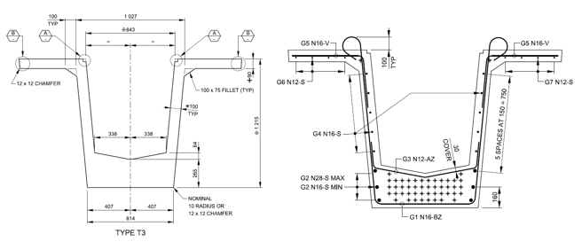 Figure 1. Super T section, strand, and reinforcement pattern
Super Tees offer greater torsional resistance and can be adjusted for various bridge widths by changing the flange widths, making them more aesthetically appealing.
Construction Methodologies
Super T girders are manufactured in precast plants where first the assembly of the reinforcing cages takes place. Then this cage is inserted in the mold, and then prestress strands are installed, and then these strands are individually tensioned using hydraulic jacks followed by the concrete pour. Once the concrete reaches transfer strength, the beam is de-stressed.
These Super T girders are transported to the bridge site. Once the pierhead reaches sufficient strength, these Super T girders are lifted and positioned onto the pierhead, followed by the diaphragm and cast-in-situ reinforced deck slab.

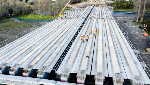 Figure 2. Construction of Super T-Girder Bridge
Modeling, Analysis and Design using midas Civil
Midas Civil has various features that can be used to model, analyze, and design various types of Super T Girder Bridges. Whether it is simply supported or continuous, skew type, integral type, or bearing type, midas civil can easily design these types of Super T girder bridges. The design methodology is highlighted below:
The webinar shows how to model, analyze, and design Super T girder bridges as per AS 5100.
The main steps are described below:
1. Define material and section properties.
In midas Civil, the material properties are included in the database as per the standard. The grade of concrete (like Australian Standard C40) can be directly selected. Various Super T girder sections are readily available in the database as per Australian and New Zealand standards, and thereby section properties are automatically calculated by the program. If we have unsymmetrical flanges of the Super T section, we also have an AutoCAD import of section using the built-in Section Property Calculator tool.
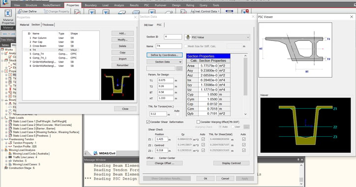 Figure 3. Section Property Calculator
2. Create a grillage model of the Super T-girder bridge including the substructure
Different ways of modeling the Super T girder bridge exist using midas Civil program. We can utilize the “Pre/Post-tensioned Composite Girder Bridge” wizard instead of creating the model from scratch using node and beam elements. This wizard takes the input of layout, sectional information, tendon information, loading, construction stage information of the particular Super T bridge and then creates the model with this data built-in. Furthermore, we also have the flexibility to edit the model after the wizard runs as per the requirements. As Super T bridges can be skewed, in the wizard, the skew angle can be provided. Moreover, the strand data of Super T sections built in the database can be readily utilized in the wizard. Overall, the wizard modeling can be quite helpful and time-saving for simple to complex geometry Super T girder bridges.
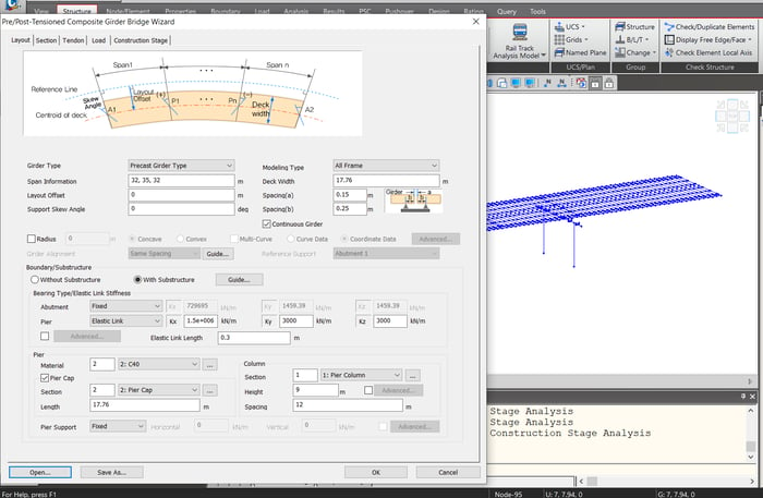 Figure 4. Pre/Post-Tensioned Composite Girder Bridge Wizard
3. Defining Construction Stages
Construction Stages(CS) will be created automatically if the wizard is used. For a typical Super T girder bridge, we follow the below construction scheme.
Stage 1: Erection of substructure
Stage 2: Erection of Precast Super T girder segments
Stage 3: Application of wet concrete load
Stage 4: Composite Action is established.
Stage 5: Super Imposed Dead Loads are applied.
Stage 6: Long-Term Effects is considered.
We shall perform linear accumulated construction stage analysis, and the results of the CS analysis will be used in load combinations with relevant load factors.
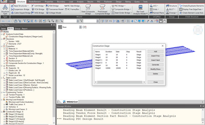 Figure 5. Construction Stage Analysis
4. Define static loads and moving loads as per AS 5100
Wind load, temperature uniform load, temperature gradient load can be calculated as per AS 5100 and then applied in the model.
Moving load analysis as per AS 5100 can be performed. It is a three-step process:
- Define Traffic Lanes
- Select the Vehicles as per the code
- Define Moving Load Cases
Moving load analysis of a Super T girder bridge entails a series of analyses for all loading conditions created along the entire moving load path (Traffic lane) to find the maximum and minimum values used as the results of the moving load cases in the load combinations.
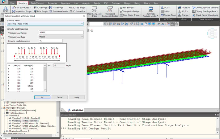 Figure 6. Moving loads analysis
5. Analyze and check results
We can auto-generate the load combinations as per AS 5100. These load combinations will include the results of CS analysis, Static analysis, Moving Load analysis, etc. Results like reactions, deformations, stresses, bending moment diagrams, shear force diagrams can be checked graphically and extracted in terms of result tables. Results can then be exported in an Excel File via the Excel Report button.
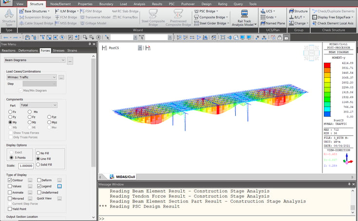 Figure 7. Analyze and check results
6. Design the girders as per AS 5100 using the PSC design feature in midas Civil
In midas civil, we can design the Super T girders using the PSC design feature. The program will perform the ultimate limit state design and serviceability limit state design as per AS 5100. After the design is performed, design results like flexural capacity, shear capacity check, stress check at service, stress check-in construction stages, etc., can be obtained. A complete design report in Excel format can be generated, including all the necessary design calculations in detail.
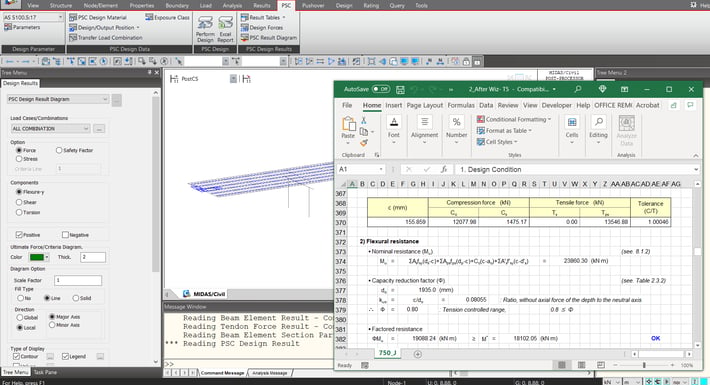 Figure 8. Design report in Excel format
MIDAS Expert Webinar


-1.png)

.png)
/Seismic%20Design%20of%20Concrete%20Bridges/Seismic%20Design%20of%20Concrete%20Bridges%20345%20240.png)
/Geometry%20Modeling%20Techniques%20for%20Bridge%20Engineers%20Seeking%20for%20More/Geometry%20Modeling%20Techniques%20for%20Bridge%20Engineers%20Seeking%20for%20More.png)