Get Started midas Civil
 Featured blog of this week

Bridge Span According to AASHTO LRFD
Please fill out the Download Section (Click here) below the Comment Section to download the Complete Guide to Composite Sections
Table of Contents
1. Introduction
2. What is a Bridge Span?
3. Bridge Span According to AASHTO LRFD
1. Purpose of Bridge Rating
AASHTO LRFD Bridge Design Specifications are used for bridge assessment, design, and rehabilitation. LRFD or Load and Resistance Factor Design pertain relatively to the superstructure and substructure’s level of safety. The level of safety varies depending on the member type, span length, and arrangement. There is such variability since the design loads and their utilization was not ciphered to result in a force effect with a similar level of safety to all the span and member types.
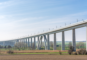
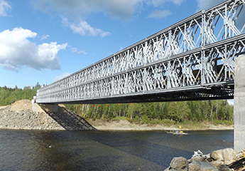
2. What is a Bridge Span
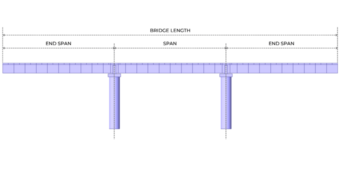
The center-to-center distance of adjacent towers, pylons, piers, or supports is called a bridge span. Bridge length however pertains to the total length of the total span of the bridge.
3. Bridge Span According to AASHTO LRFD
The safety factor in designing a bridge is simply when the requirement on the section and materials is less than that of what is supplied. Hence, when a load or load combination reaches the resistance of the section or material, failure is likely to happen.
Deterioration of wearing surfaces caused by service load deformations weakens the bridge’s durability and serviceability. According to AASHTO LRFD, in the absence of other criteria, various deflection limits may be considered for concrete, steel, and/or aluminum bridges. These deflection limits are in accordance with AASHTO LRFD 2.5.2.6.2 Criteria for Deflection. It is stated that the deflection limit is larger for the vehicular and/or pedestrian loads for cantilever arms compared to the general or usual.
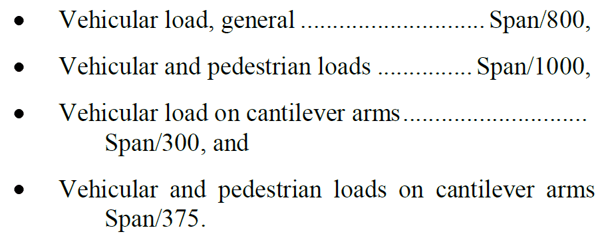
As for the deflection limits for wood construction in the absence of other criteria, vehicular and pedestrian loads are Span/425. On the other hand, the deflection limit of vehicular load on wood planks and panels for extreme relative deflection between adjacent edges is 0.10 inches.
Provisions for orthotropic plate decks shall also be applied for vehicular load in deck plate, with a deflection limit of Span/300. The deflection limit for the vehicular load on ribs of orthotropic metal decks is Span/1000, or with an extreme relative deflection between adjacent ribs of 0.10 inch.
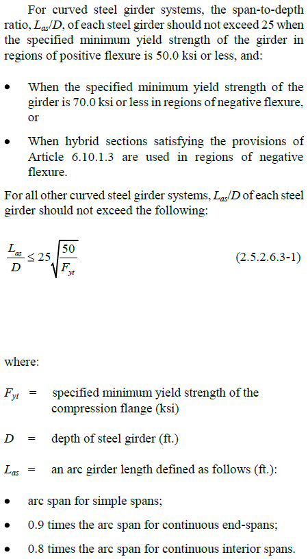
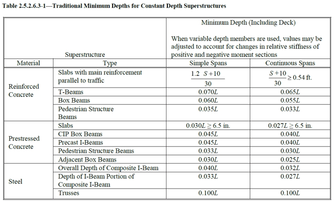
Optional Criteria for Span-to-Depth Ratios are given in AASHTO 2.5.2.6.3. The limits in Table 2.5.2.6.3-1 may be considered in the absence of other criteria and shall be taken to apply to overall depth unless noted.
For curved steel girders, a larger ideal minimum depth of girder is defined to consider the disproportionate share of loading experienced in the outermost curved girder. As for the curved skewed bridge, increasing the girder’s stiffness by increasing the depth leads to smaller relative deflection differences and cross-frame forces.
The minimum depth for constant depth of superstructures as shown in Table 2.5.2.6.3-1 for continuous spans is lesser than the simple spans. The T-Beams for reinforced concrete have a minimum depth larger than the box beams and the pedestrian structure beams being the smallest. CIP box beams and precast I-beams have the same and largest minimum depth with respect to the span length for prestressed concrete, followed by the pedestrian structure beams and adjacent box beams respectfully. For the steel, the truss type has the largest minimum depth, followed by the overall depth of composite I-beam, and the depth of the I-beam portion of composite I-beam.
The beam size particularly its height, controls the span of the beam. By increasing the beam height, the beam has more material to subdue the tension. As the distance increases, the size of the supports also increases until the weight of the bridge can no longer support itself. Hence, despite some added supports to create tall beams, the bridge is still limited in the distance it can span.


-1.png)