Get Started midas Civil
 Featured blog of this week

Bridge Insight:
Misalignment issues resolved by using Pre-Camber in Balanced Cantilever Bridge
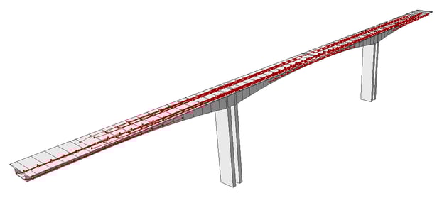
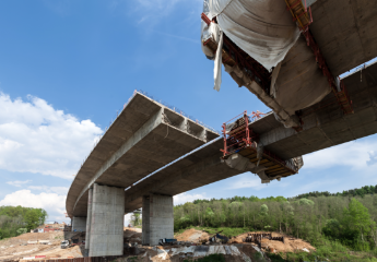
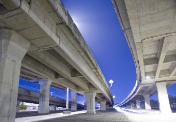
Free Cantilever Method (FCM) is generally used in a terrain where obstacles such as rivers, creeks, and roads lie under the bridge, which creates difficulties in installing conventional shoring. FCM is generally used for long-span bridges, which are typically accompanied by high piers. It is one of the most efficient methods of building bridges without the need of falsework. Since it involves constructing balanced cantilevers from a pier, it is often referred to as a balanced cantilever bridge.
Similar to any other segmental construction methods, FCM presents structural system changes in each construction stage, and each structural system needs to be analyzed throughout the construction process. The cantilevering method can be applied to both precast and cast-in-place construction. Particularly for cast-in-place construction, not only the initial load of the newly cast segment but also the age of other segments of the superstructure must be considered in the structural analysis of the erection process. In this continuous casting, different segment ages within the bridge superstructure naturally lead to different concrete strengths. Each concrete segment must possess the structural capacity to support the subsequently cast segments. The early loading of a newly cast segment usually creates a larger span deflection than a precast cantilever. As the cantilever increases, the deformation increases significantly, requiring corrective action at the construction stage.
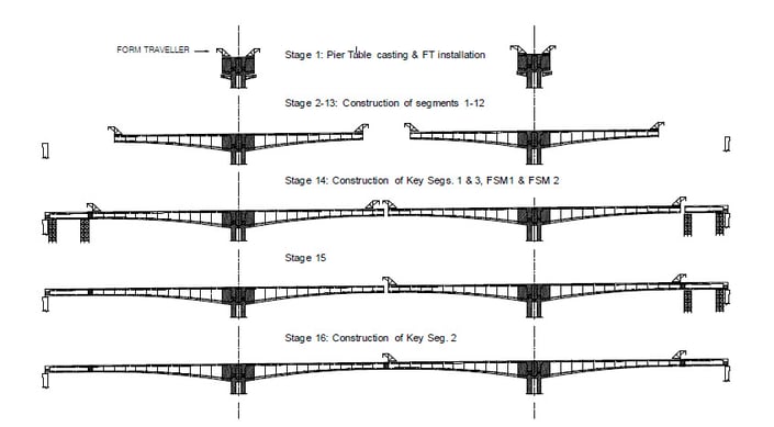 Figure 2: General Construction Sequence of Balanced Cantilever Bridge
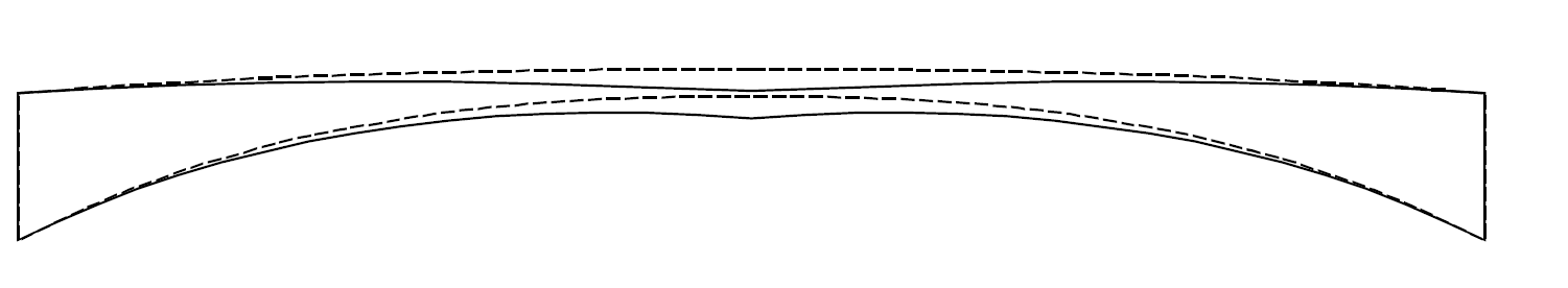
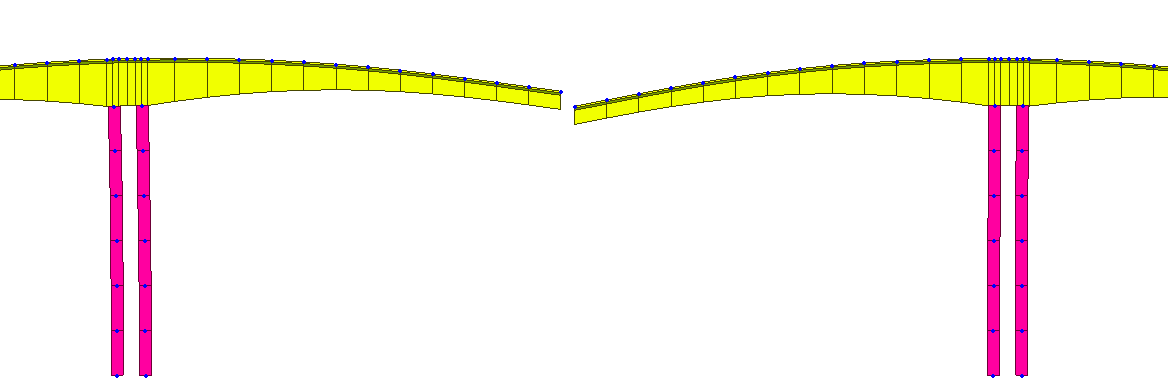
In a typical FCM construction, not all the piers (substructures) are built at the same time. As a result, the two cantilevers, which will be joined by a key segment, are not constructed at the same time, and the cantilevers have different ages at the time of erecting the Key Segment. Thus, the two cantilevers will experience different deflections at the time of erecting the Key Segment which further affects the level of driving comfort by causing a misalignment in the endpoints or a sudden sag in the middle span.
These deformation can be predicted through structural analysis of appropriate models and software. In order to get accurate deformation results at the construction stages, it is necessary to take into account the points mentioned below.
Factors Affecting Deformation Prediction:
1. Creep: Time dependent deformations of concrete under permanent loads. (Stress Dependent). Time history of stresses and time become the important factors for determining the creep.
2. Shrinkage: The time-dependent strain measured in an unloaded and unrestrained specimen at constant temperature. (Stress Independent)
3. Modulus of elasticity: The modulus of elasticity is directly influenced by material strength and, therefore, factors (like maturity age) that modify strength also affect it.
4. Prestress Losses: Friction, Anchorage Slip, Relaxation loss will heavily affect the deformations.
5. Construction Process: Simulating the segment-wise construction procedure according to its actual chronology is important. Complex loading history needs to be considered.
6. Concrete Material: Pre-defined Creep and Shrinkage models not accurate for high strength concrete and light-weight concrete, needs some experimental data to simulate it correctly.
7. Time Delays: Sensitivity of the deformations to variations in construction schedule and procedures.
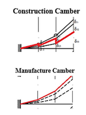
The camber of the superstructure compensates for these deflections to reach the planned alignment after construction has been completed and further time-dependent material effects have occurred.
"Camber" is a pre-calculated vertical deformation that should be considered at the construction stage (for on-site cast situations) or in the manufacturing stage (for precast segments and steel structures) in the opposite direction of the upcoming deflection to counteracts that future deflections that would come from the permanent loads.
Deformation control in the construction period:
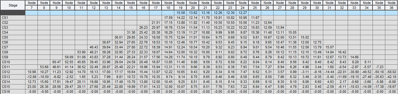
In order to calculate the camber value, the deformation at each stage of construction as well as the total displacement needs to be calculated. The measured elevation of each existing segment in each construction stage is recorded in a pyramid-like diagram. The pyramid form results as the data is recorded in rows and the length of the rows is gradually increasing at both ends as the length of the balanced cantilevers are increasing segment by segment. The diagram includes the theoretically expected value of deformation calculated by the structural analysis.
In the construction phase, the form-work is aligned according to the camber data determined during structural analysis. Control the alignment of bridges during bridge construction using shape control data from structural analysis and daily site surveys. This includes exactly meeting the two-span halves for mid-span closure. If the deflection observed in the firstly completed cantilever deviates from the expected value, it can be corrected by re-adjusting the prescribed excess height for the remaining segments of the other cantilever.
Let’s understand the Camber by a simple example:
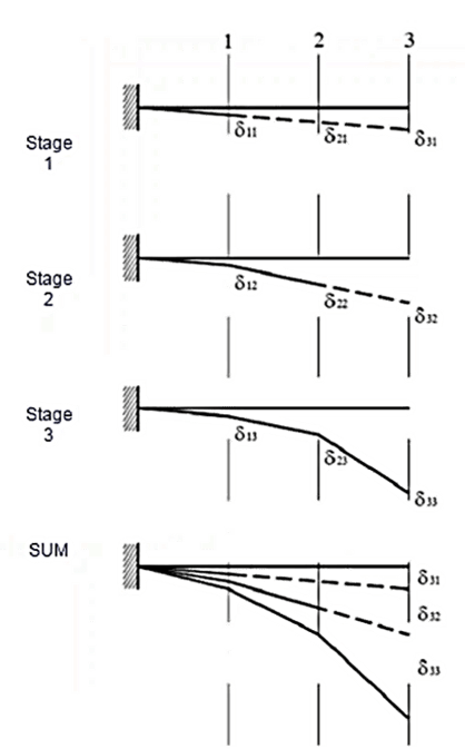
In the example below, a cantilever is constructed in 3 phases, and analysis is performed for each stage to get the deflection results at all three stages. The below diagram shows the deflection results of the individual construction stage. The final requirement is to construct the cantilever straight horizontally. To achieve the final design profile, the free camber should be provided in the direction opposite to the overall deflection.
Here,
δ11 = Deflection at node 1 due to activation of cantilever part 1 only
δ21 = Tangent Deflection at node 2 due to activation of cantilever part 1 only before activating the cantilever part 2 & part 3
δ31 = Tangent Deflection at node 3 due to activation of cantilever part 1 only before activating the cantilever part 2 & part 3
δ12 = Deflection at node 1 due to activation of cantilever part 2 only
δ22 = Deflection at node 2 due to activation of cantilever part 2 only.
δ32 = Tangent Deflection at node 3 due to activation of cantilever part 2 only before activating the cantilever part 3
δ13 = Deflection at node 1 due to activation of cantilever part 3 only.
δ23 = Deflection at node 2 due to activation of cantilever part 3 only.
δ33 = Deflection at node 3 due to activation of cantilever part 3 only.
On the basis of type of constructions the Total Net Displacement & Camber values can be categorized in the two parts:
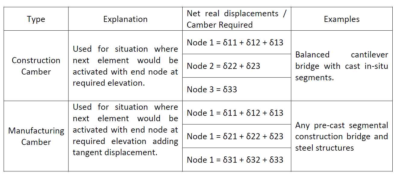 Figure 7: Total Net Displacement & Camber values
In the case of the Cast-In-Situ construction type, irrespective of the deformations of the already existing neighboring segment, when a new segment is built it has zero deformation at time zero and before loading. This corresponds to the situation in reality that the formwork for the subsequently cast segment is set at the prescribed elevation when the existing part of the cantilever has already undergone deformations. However, for precast segments or steel structures, this adjustment does not exist, so the tangent displacements should also be considered in the camber calculation.
Conclusion:
In order to achieve the design profile camber control is required in balanced cantilever construction of the bridge. For the calculation of the accurate camber time-dependent material properties, construction stage analysis, tangent displacements consideration are needs to be considered with high level of accuracy.
Midas CIVIL (Structural Engineering Software) provides us cambers results with the consideration of all the above factors by using its predefined Creep/Shrinkages & Compressive Strength time variation definitions as per various international standards, advanced construction stage analysis and tangent displacement consideration in deformations calculations. Even calculated camber can be included within the construction stage analysis so that real construction results could be seen before starting the construction of bridge.
Refer to the following link below to see the process of camber calculation in Midas CIVIL.