Get Started midas Civil
 Featured blog of this week

Please fill out the Download Section (Click here) below the Comment Section to download the 80 Masterworks of Civil Engineering
Critical Loads for Bridge Substructure as per IRC 6
Introduction
Bridges, in particular the substructure, require particular attention since they are inherently less redundant structures when compared to buildings. The substructure is the means of a load transfer system to the ground.
Different types of loads with suitable load factors are considered while designing to maintain structural integrity. Some are permanent loads such as dead loads, superimposed dead loads (SIDL), while some are transient loads/applied for short-term like vehicle loads, seismic loads, braking loads.
In this blog content, loads critical for substructure as mentioned by the code (IRC 6) and how they are considered during the analysis or design process are explained. The following loads will be discussed in detail:
- Dead Loads & Superimposed Dead Loads (SIDL)
- Moving Loads with Braking Loads
- Accidental or Collision Loads
- Wind Loads
- Water Pressure and Debris Loads
- Seismic Loads
- Earth Pressure Loads
Dead Loads & Superimposed Dead Loads (SIDL)
Dead loads are the most basic of all the loads any structure would have to resist. These include the self-weight of the structure and the superimposed dead loads, which are loads applied by railings such as crash barriers, medians, and wearing courses.
These loads are permanent and are always present till the service life of the bridge. Furthermore, dead loads and superimposed dead loads are generally transferred to the substructure using safety factors as per structural strength and serviceability.
Dead Loads are also critical for seismic analysis, which is converted into masses. Besides, time-dependent effects such as creep are also greatly influenced by the dead loads considered.
Moving Loads with Braking Loads (Cl. 204, 208, 211, 212)
As we generally know, bridges are constructed for traffic movement. Therefore, traffic loads become an essential aspect of bridge design. Traffic loads, or moving loads, are not stationary & they become important to obtain the critical vehicle position, which may cause the worst loading effect or, in other terms, may govern the design.
Critical Vehicle Position:
As a vehicle moves over the superstructure, different critical load cases are obtained, producing the envelope of results in which one vehicle position may produce maximum axial force. In contrast, another vehicle position may produce max bending moment in the substructure, so it is important to judge each critical case for the substructure, resulting in an array of results for the substructure design.
These arrays are Max & Min of Fx, Fy, Fz, Mx, My, Mz. Hence, 12 x 6 array results are obtained. Moreover, depending on the number of lanes, the different number of vehicles are placed. For example, for every lane, one class A can be placed, and for every two lanes, one class 70R can be placed. Table 6A of IRC 6 lists the vehicles loading combinations based on the number of lanes.
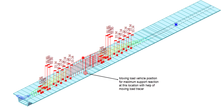 Figure 1. Moving Load Position Using Moving Load Tracer
Special Vehicle Loads:
Special vehicle loads are applied close to the center of the bridge with a maximum eccentricity of 300mm for two or more lane bridges. However, during special vehicle passage, no other vehicles should be considered. No seismic, braking or wind loads should be considered. Moreover, the impact factor should also be ignored as it moves at a speed less than 5 km/hr. The partial safety factor for ultimate structural strength and serviceability strength is 1.0 as per Cl. 204.5.
Congestion Factor:
For bridges near industries, ports, or mines, the congestion factor must be applied as per the span length of the bridge as per Cl 204.4.
Dynamic Effects for Live Loads as per Cl. 208:
Dynamic effects are accounted for by applying the relevant impact factor. The impact factor depends on the type of bridge (whether it is steel or concrete), type of vehicle (class A, class B, or class 70R), and bridge span length. No impact factor is to be applied for footway live loading. These impact factors do not apply to suspension bridges or foot over
bridges but are considered for the cable-stayed bridges where the ratio of live loads to dead loads is relatively high.
Tractive Loads & Braking Loads as per Cl. 211:
Tractive loads are caused by the vehicle's acceleration, and the braking loads are caused due to the braking of the vehicle. These loads are the horizontal loads applied to the superstructure, which are transferred to the substructure.
When the bridge has 1 or 2 lanes, the braking load is 20% of the leading vehicle and 10% of all the preceding vehicles. When the leading vehicle is not entirely on the span, 20% of the load present in the vehicle should be applied. Furthermore, the impact factor should not be applied to the load for the calculation of braking load. This factor should be applied 1.2 m above the roadway. Moreover, depending on the type of support, the longitudinal distribution of braking forces on bearing changes.
Within the software, during analysis, the braking load can either be applied at critical vehicle location as horizontal point loads or, as in general practice, applied as a uniform horizontal load in the longitudinal direction, with vertical eccentricity as shown below.
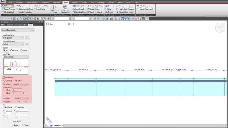 Figure 2. Braking Load Applied at an Eccentricity from Load > Static Load > Element Beam Load > Uniform Load
Centrifugal Forces:
Centrifugal forces are generated when a bridge has a curvature. Centrifugal forces are applied at the height of 1.2m above the carriageway's height at the point of action of the wheel or uniformly distributed for the uniform live load over the length. The impact factor effect is ignored.
The centrifugal force is calculated as:

where,
W is the live load (tons), V is the velocity (km/hr), and R is the radius of curvature (m).
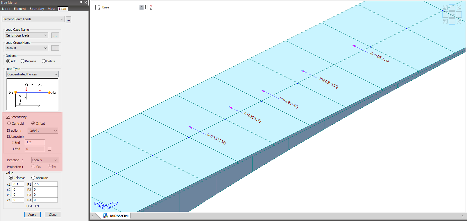 Figure 3. Centrifugal Load Applied with Eccentricity on Deck at the Location of Axles
Accidental Loads/Collision Loads (Cl. 222)
Accidental or Collision Loads are those loads that are directly applied to the pier or substructure. They are considered to either act normal or parallel to the carriageway and should not be combined. The supports resist main and residual load components simultaneously. Furthermore, these loads given below are applied for vehicle speeds greater than 60 Km/hr. If the vehicle speed is less than this value, it is reduced by the square of the velocity until 50%. If a bridge is designed for residual factor only, consider it at a minimum of 1.5 m above the carriageway level.
|
Component |
Normal (tons) |
Parallel (tons) |
Application point |
|
Main |
50 |
100 |
Between 0.75 to 1.5 m above carriageway with most critical condition |
|
Residual |
25 |
50 |
Between 1 to 3 m above carriageway with most critical condition |
The effect of collision load should not be considered for the abutment. Furthermore, it should not be combined with principal live loads as well as seismic or wind loads.
 Figure 4. Collision Load Applied on Substructure at Critical Locations from Loads
Wind Loads (Cl. 209)
Wind loads are lateral loads that are critical in transverse direction since bridges have less resistance in the transverse direction. One should note that wind forces defined as per code are for bridge spans of up to 150m and pier heights of up to100m. Beyond this, the bridge may be considered dynamically sensitive, and advanced analysis or wind tunnel testing may be needed.
Wind pressure applicable at any location is dependent on its geographical location, terrain of the surrounding area, fetch of terrain upwind of bridge location, local topography, height of the bridge above ground, cross-section of bridge elements, and horizontal dimensions (contact area in simpler words). They should be considered to act, causing maximum stresses for members under consideration.
Based on the basic wind speed map and geographical location, the wind speed and pressure are calculated for different bridge components.
For construction stages, 70 % of wind speed calculated as per Cl. 209.2 should be considered during construction stage analysis.
Wind Loads on Live Loads:
If wind speed is greater than 36m/s, wind loads on live loads are not considered. Therefore, two scenarios are considered: Firstly, with 36m/s as wind speeds present on live loads. Secondly, normal speed neglected on the live loads. An envelope of results is obtained for critical forces as per Cl. 209.3. Wind loads in the vertical, longitudinal, and transverse directions of the bridge should be applied simultaneously.
The transverse wind force is calculated as:
F = Pz x A x G x Cd
where,
Pz is the wind pressure, A is the area of the location, G is the gust factor (kept as 2), and Cd is the drag coefficient which depends on the geometrical shape of elements/superstructure.
Drag coefficients (Cd) for the superstructure may vary on the type of bridge, width to depth ratio of the bridge, and the number of girders. The drag coefficient for the calculation of the wind force is 1.2. Drag coefficient on piers depends on the height to breadth ratio of the pier and plan shape of the pier, as given in Table 13.
Transverse wind forces are applied at the centroid of the superstructure and substructure. For live loads, the exposed frontal area is considered as the bridge length x 3 m (assumed height of the live load) and is applied at 1.5 m above the carriageway. The longitudinal wind force is taken as 25% of transverse force on the superstructure for beam/box/plate girder bridges, 50% for truss girder bridges, and 25% for live loads. Transverse forces for bridge substructure are calculated similarly to longitudinal forces in which width and breadth of pier cross-section changes\ accordingly as per Cl. 209.3.4.
Furthermore, for calculating critical loads due to wind loads, both wind loads on the substructure and superstructure should be considered simultaneously. Moreover, the load's directions from the superstructure should be considered normal and skewed to the longitudinal centerline of the superstructure.
Water Pressure and Debris Loads (Cl. 210)
Water pressure loads are applied to only bridges constructed on the waterfront. The intensity of the water pressure parallel to the water current is computed as below:

where,
V is the velocity of the water current at the location, and k is a constant depending on the pier's shape.
The zero-velocity of the water current is considered at the point of deepest scour, and velocity at the topwater surface is considered as √2 of the maximum mean velocity.
When the water current is not parallel to the pier, velocity is divided into parallel and normal components. The parallel component is calculated as earlier, but the normal component of pressure is calculated using the normal velocity component. Still, the k value is 1.5 for all the piers except for circular piers, whose k value is 0.66. Furthermore, the variation of the angle of 20 degrees for the actual current direction should be used to calculate critical results.
Seismic Loads (Cl. 219)
Bridges Critical for Seismic Loads:
Bridges are to be designed for seismic loads other than culvert or minor bridges with a span of fewer than 10 m and bridges in zone 2 and 3 with spans less than 15m and a total length of 60m. Furthermore, additional research must be conducted for long-span bridges and bridges having high pier lengths in seismic higher zones.
Seismic Response Calculations:
The seismic response is generally calculated using the elastic response spectrum method. For the horizontal seismic force,

where,
Ah = horizontal seismic coefficient

Z = zone factor, I = importance factor, and Sa/g = Average response acceleration, which depends upon the fundamental periof of vibration, T. If detail calculation for the cracked section is not performed, the moment of inertia for calculation of time period is kept as 0.75 * I (cracked section)
Horizontal seismic forces for live loads are considered only in the direction perpendicular and vertical to the vehicle movement, and is considered for 20% of the live load without the impact factor. Time period of pier/abutment of the bridge along the horizontal direction is:

where,
D is the dead load + 20% of the live load in kN, and F is the horizontal force in kN required for 1mm horizontal deflection for top of pier/abutment
Average Acceleration Response (Sa/g):
Depending on the type of soil and time period, the average acceleration response (Sa/g) is obtained. For small bridges, it is generally taken as 2.5. IRC 6 provides the Sa/g values for damping of 5%. Thus, if the structure is prestressed, steel or composite steel, then the damping of structure is 2%, and thus Sa/g value is modified by 1.4 times while for retrofitting of old bridges, damping is considered as 10%, and thus Sa/g is modified as 0.8 times.
Importance Factor:
Seismic design force multiplied by the importance factor I is applied, which depends on the bridge’s partial and complete non-availability after the seismic events. It accounts for all the seismic zones.
The part of the bridge foundation that is not in contact with the soil is considered part of the substructure. Furthermore, response reduction is taken as 1 for RCC, PCC, and masonry structures when an elastomeric bearing is used. Ductile detailing is vital for bridges in a zone higher than 2, and its response is needed to be reduced to include the effect of inelastic properties of the structure.
Earth Pressure Loads (Cl. 214)
Structure such as abutments, the walls of box culverts must withstand the earth pressure and are designed to retain earth fills. IRC 6 proposes to use Coulomb’s theory for non-cohesive soils, and for cohesive soil, Columb’s theory with Bell’s correction is to be used.
Lateral earth pressure on the bridges is applied depending on the situation where they are expected to move or not. Like in abutments, where there is soil on one side of the wall, it is expected to move. Accordingly, active/passive earth pressure forces are applied. In the case of box culverts, the soil is present on both sides & hence the structure does not move. Therefore, at rest condition is used for the calculation of the earth pressure.