Get Started midas Civil
 Featured blog of this week

1. Definition and meaning of Camber
In the dictionary, Camber is defined as "a raised surface or a member raised upward." In other words, it means ‘to bend higher than the original/target shape’.
In the field of structural civil engineering, it is most appropriate to define a Camber as "a member that is made in advance by maintaining a stress-free state so that the member can become the intended(target) shape at a certain time." Reviewing this definition reveals the following two factors:
First, when calculating a camber, the definition of a Target Shape and the Time of the Target Shape must be premised. Camber is a function of time (absolute time and loading time of a load) that varies with stiffness and load, except when the material and behavior of the structure are designed to remain in a perfectly elastic state. Therefore, when the camber is calculated, the shape of the structure has a certain point in time that matches the target shape. It is customary to calculate the camber based on N days after construction completion, which is at Infinity Time. In theory, it means that the structure shows a deviation from the target shape at the point of time after construction is completed, and it becomes the same as the target shape only after N days have passed after construction is completed.
Second, the state in which the camber is applied is a stress-free state. In other words, it is a reference state in which there are no deformations and stresses. Thereafter, as various loads and time are applied, the structure is subjected to deformation and stress. Therefore, based on the target shape the camber is considered, and once it is considered, the deformation calculation is applied to the structure at the time of design. Here, the deformation is canceled out and has no effect on the stress. For this reason, designers consider the target shape as a reference state, analyze it, and conduct structural reviews. However, it should be taken into consideration that special types of structures, (typically cable-stayed bridges) other than girders, can be nonlinear problems that are cyclically affected by the following order: camber --> deformation+stress --> camber.
Usually, cambers are not the primary concern for designers. When I looked back on my days as a designer, I believed a camber was an incidental output that came when the design of a structure was almost completed, but now that I am a contractor, I firmly believe it is a very important design result. This is because failure to accurately calculate and construct the camber interferes with the serviceability of the structure. However, inaccurate camber calculation and poor camber construction may cause anxiety or discomfort to users (drivers when considering bridges) and reduce the durability of the bridge appurtenant (cable system, supports, expansion joints, etc). Therefore, in the long run, and in an economical standpoint, the implementation of cambers is something that both the designers and contractors should not overlook.
2. Camber classification
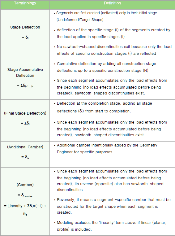
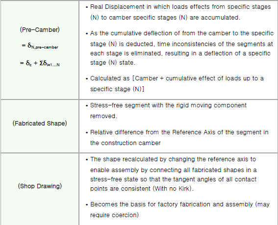
Some might wonder, “Are there different kinds of cambers?” What I referred to as ‘Camber classification’ is not literally ‘to sort the different classification of cambers’, but to reflect my thoughts on conveying the exact definition and meaning of ‘camber related terms’ to designers and constructors. The following table summarizes the terms associated with cambers.
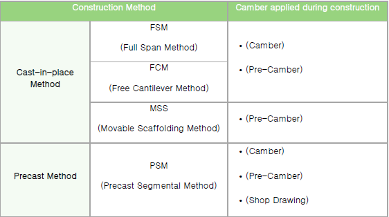
Shop Drawing is a construction method for prefabricated structures such as steel girders, precast, etc, and Camber is essential for cast-in-place construction methods (in this case, the shop form and drawings don’t exist). This is summarized in the following table.
3. PSC Girder Camber calculation
-
Camber calculation method
Most structural analysis programs using the Finite Element Method (FEM) create new segments/elements for each stage based on their initial stage (Undeformed/Target Shape). That is, the segments/elements before the current stage have deflection (displacement) and cross-sectional force under load, but the segments/elements at the current stage are created in an initial stage excluding the effects before the current stage. Therefore, the shape of the deflection in the final stage has a sawtooth-shaped discontinuity.
By taking the inverse of this shape, the camber in the general case (linear and no additional cambers) is calculated.
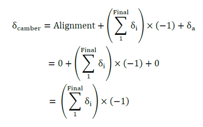
-
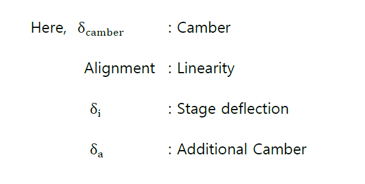
Pre-Camber Calculation Method
As mentioned in the previous section, the Camber obtained through a general structural analysis program not only has discontinuities, but also each segment/element represents a different stage. Therefore, it is necessary to calculate the smooth (continuous) displacement from the segments/elements created in the first stage to the segments/elements created in the current stage. This displacement is called ‘Pre-camber’ or ‘Real-Displacement’ and is calculated using the following equation:
-
Shop Drawing Calculation Method
Details on shop drawing will be covered in another post, and in this post, only the calculation method will be briefly mentioned. In general, the shop drawing can be calculated through the following method.
1) Calculate the Camber
2) Rigid movement and rotating components are removed from the camber. In other words, one point on the structure is set as a reference point, and then all Fabricated shapes are connected by tangent lines.
3) Change the reference axis to enable preassembly by referring to the connected shape in 2), and recalculate the connected shape in 2) to obtain the Shop Drawing.
4. Example of Camber Calculation for PSC Girders
In order to examine the camber calculation process in detail, let’s take a two-span PSC girder of the FSM Method, which is constructed in two stages as shown in the following figure. In the example model, the two stages (considering only 5 times its own weight) were divided and the time-dependent properties of concrete (creep and drying shrinkage) were ignored.
/Contents/Bridge%20Insight/new%20image%20Definition%20and%20Calculation%20of%20Prestressed%20Concrete%20Bridge%20Camber%20Considering/Example%20of%20Camber%20Calculation%20for%20PSC%20Girders.png?width=734&name=Example%20of%20Camber%20Calculation%20for%20PSC%20Girders.png)
Using the analysis results of the example model, each step is calculated according to the camber classification table in Chapter 2, and the results are shown in the following table.
/Contents/Bridge%20Insight/new%20image%20Definition%20and%20Calculation%20of%20Prestressed%20Concrete%20Bridge%20Camber%20Considering/Example%20of%20Camber%20Calculation%20for%20PSC%20Girders%202.png?width=734&name=Example%20of%20Camber%20Calculation%20for%20PSC%20Girders%202.png)
/Contents/Bridge%20Insight/new%20image%20Definition%20and%20Calculation%20of%20Prestressed%20Concrete%20Bridge%20Camber%20Considering/Example%20of%20Camber%20Calculation%20for%20PSC%20Girders%203.png?width=734&name=Example%20of%20Camber%20Calculation%20for%20PSC%20Girders%203.png)
Conclusion
Chapter 1 summarizes the definition and meaning of a camber, and Chapter 2 categorizes and explains what a camber is. Chapter 3 explains how to calculate the camber of a PSC girder, and in Chapter 4, FSM 2-span PSC girder was used as an example to calculate the ‘stage deflection’ all the way to the ‘shop drawings’ according to Chapter 3.
For designers, camber calculations may seem less important than securing safety and usability through structural review. However, inaccurate camber calculation and poor camber construction may cause anxiety or discomfort to users (drivers when considering bridges) and reduce the durability of the bridge appurtenant (cable system, supports, expansion joints, etc). Therefore, I hope this article will give you an opportunity to recognize that the calculation and implementation of camber is an essential factor for designers/contractors.