Get Started midas Civil
 Featured blog of this week

Please fill out the Download Section (Click here) below the Comment Section to download the Model File
Dynamic Analysis of Fan, Semi-Fan, and Harp Type of Cable-Stayed Bridges
While modeling cable-stayed bridges, the different types of cable arrangements such as Fan, Semi-Fan, and Harp type is often considered. Since they vary in cable arrangement, the pretension in the cables is different and the deflection, bending moment, and stresses vary in the bridge. It then becomes prudent to choose the best arrangement for a more optimized design leading to lesser cost and increased safety.
In this article, we present, in a concise way, the modeling of a Cable-Stayed Bridge in midas civil with three different cable arrangements. Furthermore, Response Spectrum analysis is carried out on the models to study the Dynamic Responses of the three arrangements.
Table of Contents
1. Concept of Cable-Stayed Bridge
2. Different Arrangements of Cable System
3. Finite Element Model of the Bridge
1. Concept of Cable-Stayed Bridge
The development of Finite Element Software has promoted the application of cable-stayed bridges. This is due to the high redundant Degree of Freedom number related to the number of cables which could not be solved manually; however, it is now possible by FEM software.
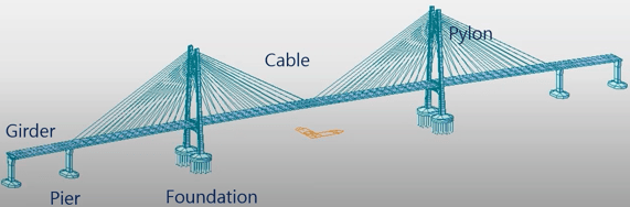
Commonly, a cable-stayed bridge has five components.
a) Girder : PSC/Steel/Composite
b) Cables: mainly parallel wire strands (PWS)
c) Pylon: mainly RC, some are PSC or Steel
d) Pier: mainly RC
e) Foundation: mainly pile foundation
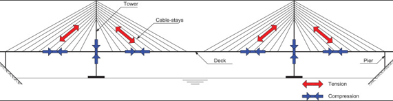
The concept of a cable-stayed bridge is simple. A typical bridge has vertical loads acting on the girders, and stay cables in this bridge provide intermediate supports to the girder so that it can span long distances. All the members of a cable-stayed bridge are predominantly under axial forces, with cables under tension and both the pylons and the girder under compression.
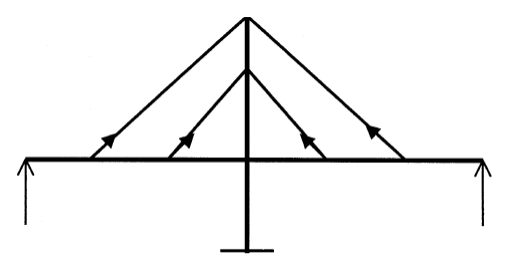 Figure 3: Force distribution in a Cable-Stayed Bridge
Since axially loaded members are generally more efficient than flexural members, a cable-stayed bridge is highly economical for higher span lengths and can range more than a kilometer in length. However, with all its advantages, cable-stayed bridges are normally sensitive to dynamic loadings like earthquakes.
2. Different Arrangements of Cable System
Cable-stayed bridges have commonly three different types of cable arrangements. These are Fan, Semi-Fan, and Harp types of arrangements. The figure below shows the cable arrangement as well as the typical Side-span to Mid-span ratio in these arrangements.
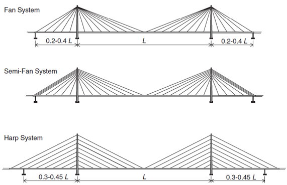
Fan System:
In this arrangement, the cables connect to or pass over the top of the towers. The cables having, a relatively steeper slope, resulting in a smaller cable cross-section as compared to the Harp type. However, when the number of stay cables increases, the weight of the anchorage increases considerably, making it difficult to attach all the stay cables together at the pylon. Therefore, Fan patterns are suitable only for spans having moderate lengths and with limited stay cables.
Semi-Fan System:
In this arrangement, the cables are concentrated in the upper part of the pylon, and they are more steeply inclined as we move closer to the pylon (Bernard et. al., 1988). This is one of the most common arrangements and the world’s largest cable-stayed bridge, the Sutong Bridge in Jiangsu, China, was designed considering the Semi-Fan arrangement.
Here, the cables are spaced from each other sufficiently as compared to the Fan system to allow better termination and offer easy maintenance of cables.
Harp System:
In the Harp system, the cables are nearly parallel to each other and is sometimes called parallel design. This arrangement is aesthetically more pleasing; however, it requires taller pylons to fit all the cables. Furthermore, since the cables are not steep, the compressive force developed in the deck is high and results in higher bending moment in the pylons.
3. Finite Element Model of The Bridge
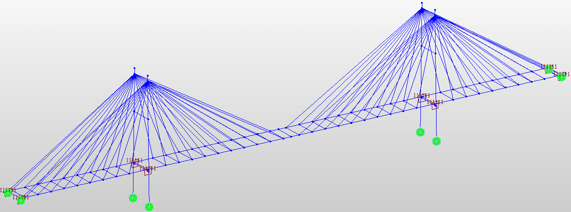
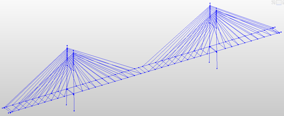
3D Finite Element Model of the bridge was prepared using midas Civil. The girders and pylons and cross-beams are modeled as beam elements (frame elements) and the stay cables are modeled as truss elements. This is because, during Response Spectrum Analysis, cables would be converted to equivalent trusses.
In midas civil, we have two element types to be considered for stay cables, trusses, and cable elements. Trusses can be used for both linear and non-linear analysis. Cable elements are auto-converted into Equivalent trusses in case of linear analysis and Elastic Catenary elements in case of Geometric nonlinear analysis. In the Equivalent Truss Method, the Ernst formula is used, where the tension truss with Sag effect is considered.
A three-span continuous cable-stayed bridge having span lengths of L =100 + 220 + 100= 420 m and lane width of 15.6 m has been modeled in midas Civil as Fan, Semi-fan, and Harp types of cable arrangements. The cable-stayed bridge Wizard in midas Civil was used for modeling which allowed for easy generation of models.
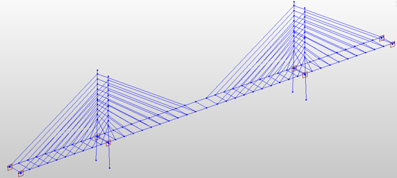
The images below show the three geometry arrangements of the cable-stayed bridge. These were modeled keeping the span length, girder and section dimensions, cable diameter, etc., constant with the only variation being in the cable arrangements.
Unknown Load Factor
The Unknown Load Factor method in midas Civil is a feature with which we can calculate the cable pretension force that would satisfy certain constraints in terms of displacements, bending moments, etc. This function optimizes the tensions of cables at the initial equilibrium position of a cable structure
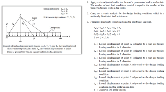
In this method, we formulate an objective function consisting of unknown load factors. The function could be formed as Linear, Square, or Max Abs summation of Load factor X scale factor. We can also choose the sign of the unknown load factors to be calculated. They can be positive, negative, or both. Since cables are always in tension, we provide the sign of Unknown Load Factor as Positive in midas Civil.
Cable Force Tuning
The cable pretension (or Load Factor) from the unknown load factor method might not be practical or might exceed the cable force tolerance limit. Hence, cable fine-tuning is done to optimize the pretension forces in the cable.
5. Loads Applied on the Bridge
Cable-stayed Bridges have become very common for large spans and are now used in earthquake-prone areas often. They are sensitive to dynamic loadings such as earthquakes and need to be analyzed thoroughly. In this model, Response Spectrum analysis has been carried out based on Eurocode-8(2004). Self-weight and additional dead loads have been applied to account for utilities, railing, etc.
6. Results of Fan, Semi-Fan, and Harp Type of Cable-Stayed Bridge
Since the bridge is symmetrical, an identical initial cable prestress will be introduced to each of the corresponding cables symmetrical to the bridge center. ULF is being carried out and the Cable tuning optimizes the initial pretension in the cables in all the three arrangements and all three models have been provided with similar cable pretension. A Load Combination called LCB1 is formed having Self-weight and Additional Load with a factor of 1 and all the Cable Pretension Load is obtained after ULF and Cable Tuning.
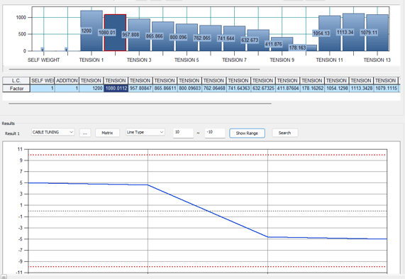
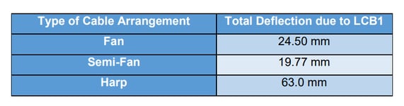
A. Total Deflection due to LCB1
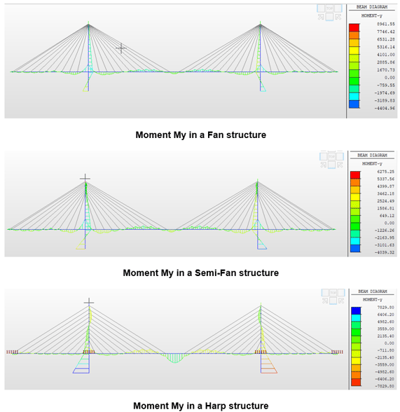
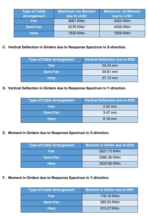
B. Moment My in the Bridge due to LCB1
7. Conclusions
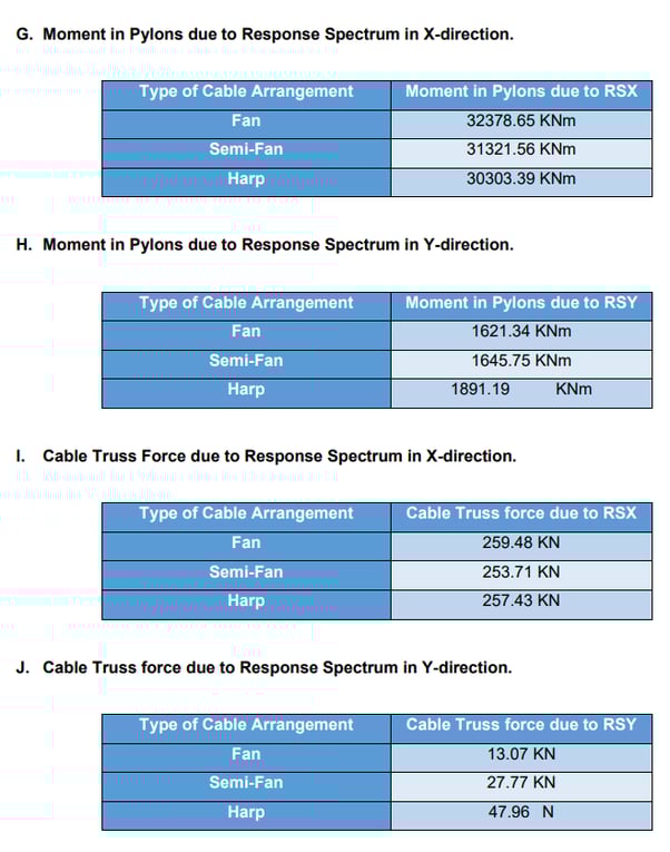
The dynamic behavior of the cable-stayed bridge was analyzed using the Response Spectrum method. For Load Combination LCB1, the Semi-Fan type of the cable-stayed bridge arrangement has given the least deflection of girders and also the minimum moment in the girders and pylons. This makes the arrangement one of the most common arrangements we come across and also the most sort-out cable arrangement.
The semi-fan arrangement is most used for long-span bridges. Harp arrangement usually gives the maximum nodal displacements and bending moment which makes it most unsuitable for long-span bridges. The only advantage of the Harp arrangement is its aesthetical appearance. Fan arrangement becomes unsuitable because of the practical difficulties in connecting all the cables to one point at the top of the pylon.