Get Started midas Civil
 Featured blog of this week

🗂️ Download Now
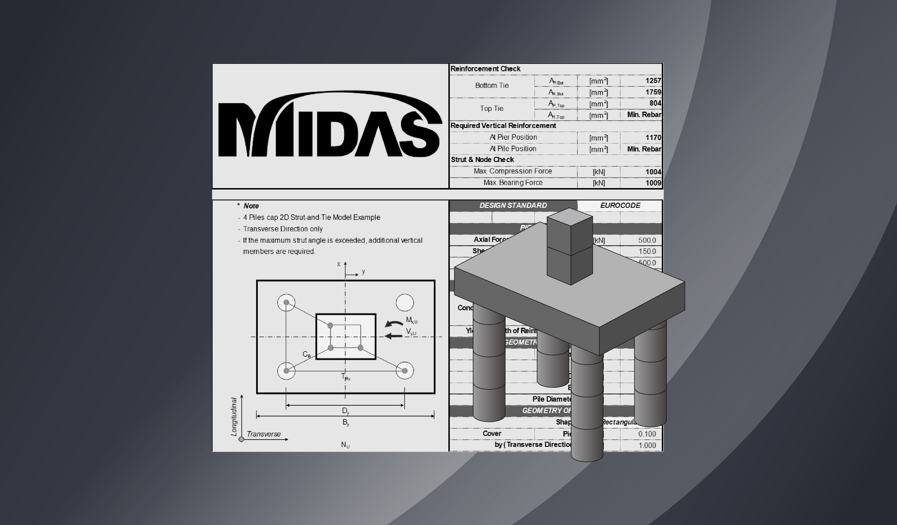
Please fill out the Download Section below the Comment Section to download the 2D Strut-and-Tie Model for the 4 Piles Cap Calculator.

1. What is a Strut-and-Tie Model?
Part 1 explores the basic concepts of the Strut-and-tie model (STM), and Part 2 attempts to describe the process of designing a pile cap using the Strut-and-tie model in 2D and 3D STM.
The Strut-and-tie model (STM) is a generalization of the truss analogy, a concept used in shear design applied to all parts of the structure. The basic concept of the generalized truss analogy states that the flow of the force within a reinforced concrete structure is the same as the flow of the force within a truss model. Furthermore, this truss model comprises a compressive stress field and a tension tie, which connects the compressive stress field.
Structural members can be divided into B-regions (Beam or Bernoulli) and D-regions (Discontinuity or Disturbed). Unlike the B-region, which undergoes beam action, the strain in the D-region undergoes arch action and has a nonlinear distribution. Moreover, because the arch action significantly increases the shear strength, it cannot be evaluated in the same way as the B-region. For this reason, the Strut-and-tie model presented a generalized design method for the D-region in situations where the evaluation for the design of the D-region is not correctly performed, and it is inevitable to rely on the designer’s experience.
-
B-region and D-region
-
General structural members can be divided into B-region (Beam or Bernoulli region), where linear strain and beam theory are applied, and D-region (Disturbed or Discontinuity region) where beam theory is not applied due to applied concentrated loads or discontinuous cross-sections.
-
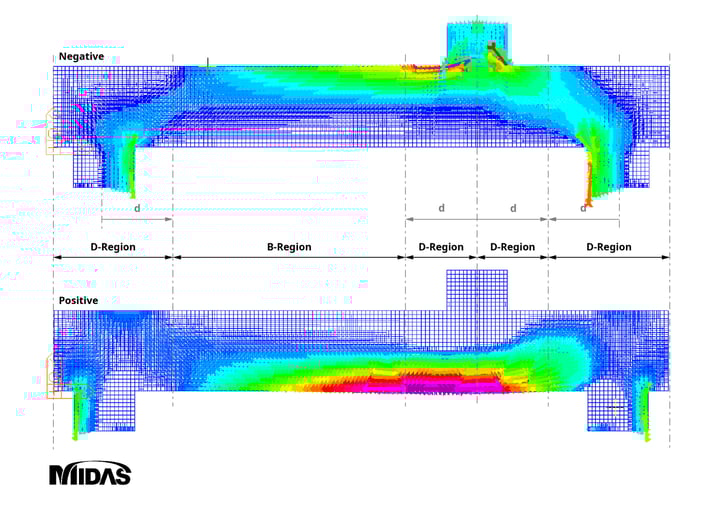 Figure 1: Stress Trajectories within B-regions and D-regions
2. Historical Development of the Truss Model
Starting with the truss analogy concept, the Strut-and-tie model is the generalization of the truss model, which has been continuously researched and developed to be applied to the design of all concrete members.
A. Truss analogy concept (Ritter, 1899)
The truss analogy concept is an early concept that describes the flow of force after cracking in a concrete member using a truss model, as shown in the figure below. Ritter’s truss model consists of the following components:
- A compression zone (upper chord) bearing the compressive stress acting on the member, and an inclined diagonal compression strut (diagonal member of the truss) on the member axis.
- A stirrup (vertical member) bears the vertical components of tensile stresses, and the bottom reinforcement (lower cord) bears the horizontal components.
This method is designed by expressing the strength of members as a truss model and obtaining the axial forces of each member. Since the flow of forces is well represented, the method is advantageous in understanding members subjected to shearing forces and in the design of shear reinforcement.
B. 45-Degree Truss Model
Ritter and Morsch assumed that the diagonal compression strut angle of the cracked concrete member was 45 degrees. In 1922, Morsch knew that the 45-angle inclination used in the stirrup design was too safe; however, he could not find a way to evaluate the slope angle for the secondary inclined crack, so he proposed a 45-degree design.
For economical design, ACI proposed adding concrete contribution to the shear reinforcement resistance of a 45-degree truss model.
C. Variable Angle Truss Model
The variable angle truss model is a method that allows the inclination angle of the compression strut to have a different value from the 45-degree within the limited range based on the limit analysis. This means that the diagonal compression strut has an inclination angle of less than 45 degrees due to the aggregate interlock and dowel action, increasing the role of the stirrup. Here, the aggregate interlock and dowel action are shared by the concrete. This approach allows for changes in slope angles but does not directly consider the share of concrete.
D. Modified Truss Model
Unlike the variable angle truss model, the modified truss model directly considers the share of concrete. As a result of several shear tests, the need to consider these effects became known, and a test method was suggested.
E. Plastic Truss Model
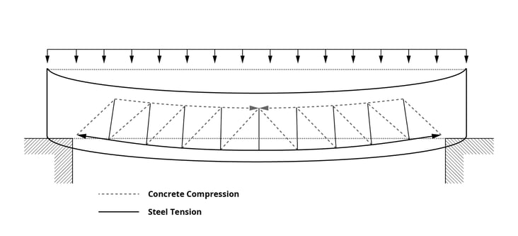
When designing concrete members, it can be assumed that the stirrup yields first and transmits the force along the crack surface before the concrete breaks. In this state, the truss becomes a statically determinate structure and does not depend on the plastic behavior of concrete members. As shown in the figure below, the equivalent plastic truss model shows the truss under the assumption that the stirrups yielded first. The diagonal compression strut of this truss model consists of a compression fan and a compression field.
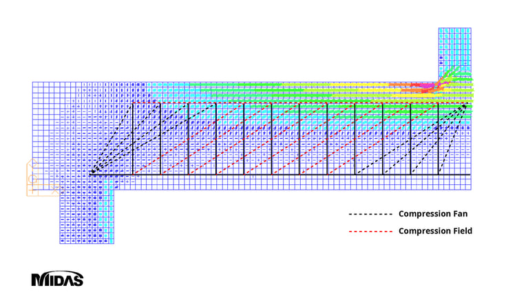 Figure 3: Equivalent Plastic Truss Model
The Plastic truss model was generalized by Schlaich in 1987 as a Strut-and-tie model applied to all parts of a structure.
Subsequently, research to determine the inclination angle of the diagonal compression strut for shear design developed into the compression field theory (CFT) and the modified compression field theory (MCFT). The modified compression field theory has become an important concept currently used in today’s design criteria.
3. Components of a Strut-and-Tie Model
As shown in the figure below, the flow of forces after concrete cracking can be expressed as a strut-and-tie model composed of compression strut, tension tie, and nodal zones. A description of each component is as follows:
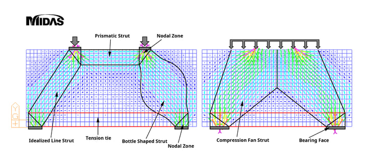 Figure 4: Components of Strut-and-Tie Model
 A. Strut
-
An STM member that expresses a compressive stress field under compressive forces.
-
The strut's shape is generally expressed as a prismatic strut or fan-shaped strut, as shown in the figure above. However, it can also be expressed as a bottle-shaped strut.
-
When bottle-shaped struts are applied to the design, longitudinal cracks may occur due to tensile forces acting perpendicular to the struts, so confining reinforcement should be placed in the direction perpendicular to the strut axis. For simplification of design, bottle-shaped struts are typically idealized as straight struts.
-
Strut capacity is a function of the effective compressive strength of concrete and is affected by concrete’s strength, load duration effect, transverse tensile strain, and cracking.
-
The nominal strength of the struts applied to the strut design shall be determined by the design criteria, and the smaller of the values calculated at both ends shall be applied to the design.
B. Tension tie
-
A tensile member subjected to tensile forces in STM.
-
Ties are placed in the center of the tensile rebar.
-
The location at which the struts and ties meet is expressed as a triangular nodal zone. The width of this nodal zone is determined by the ties and is referred to as the effective width of the tie. When more than one row of tensile reinforcing bars is arranged, the effective width of ties proposed in the design criteria is followed, as shown in the figure below.
.jpg?width=716&name=Effective%20Width%20of%20Ties%20(AASHTO%20and%20Eurocode).jpg) Figure 5: Effective Width of Ties (AASHTO and Eurocode)
Figure 5: Effective Width of Ties (AASHTO and Eurocode) -
Tie settlement should be reviewed from the location where the extended nodal zone and the center of the ties meet.
-
The extended nodal zone refers to the area where each effective width overlaps at the location where the struts and ties meet.
C. Nodes
-
In STM, the point at which at least three forces gather for force equilibrium is called a node.
-
Nodes can be divided into CCC, CCT, CTT, and TTT (C is for compression strut and T is for tension tie), depending on the type of force applied at the nodes.
-
Conceptually, nodes can be idealized as pinned joints.
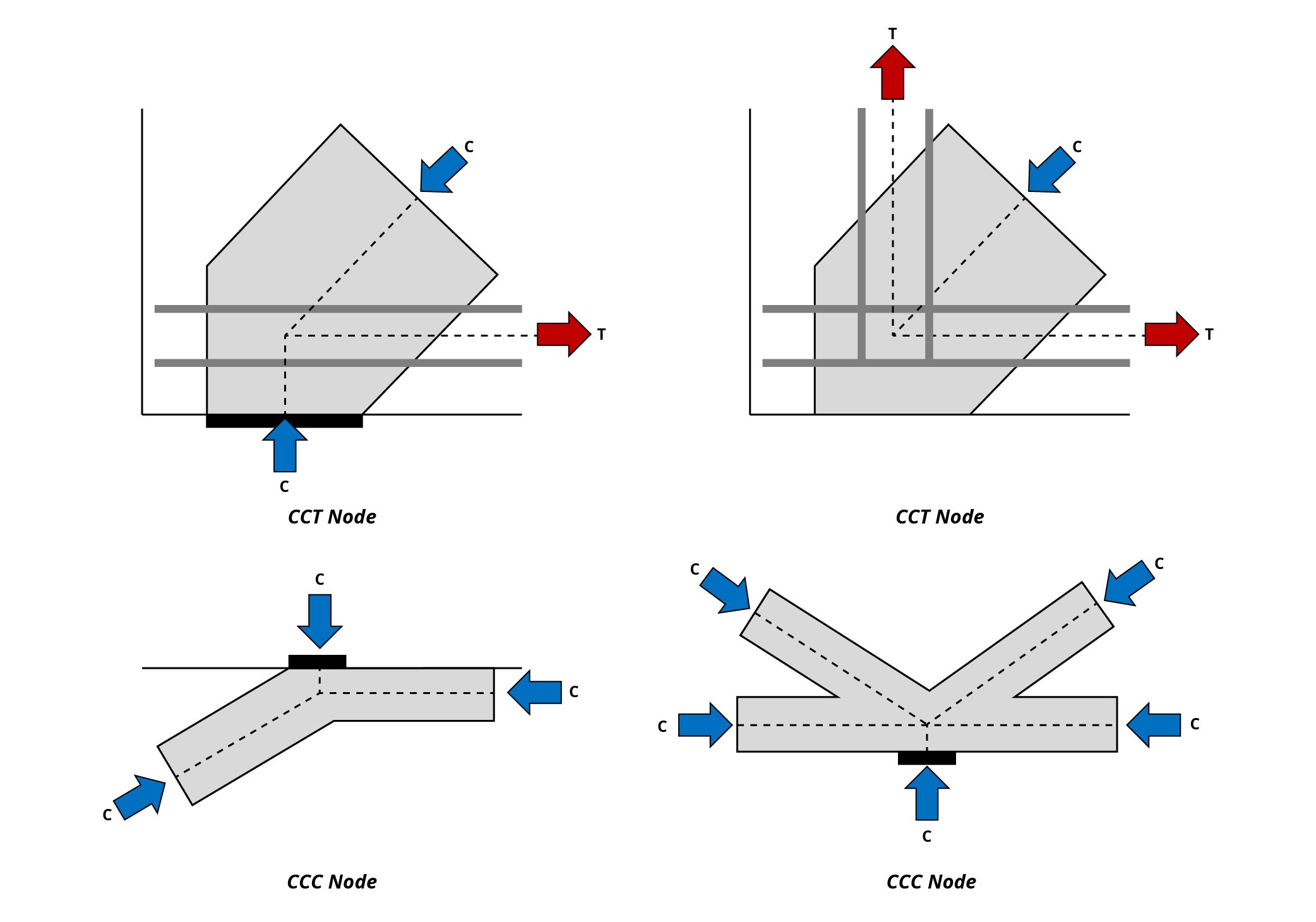 Figure 6: Types of Strut-and-Tie Model Nodes
D. Nodal Zones
-
The concrete area at the node position that allows the strut and tie forces to be transmitted through the node is called the nodal zone.
-
Hydrostatic nodal zones are zones where the sides of the nodes are placed perpendicular to the strut and ties so that all sides of the nodes have the same stress. When nodes are arranged in the Hydrostatic nodal zones, the ratio of the width of each node (w1:w2:w3) is equal to the ratio of the three compressive forces (C1:C2:C3), which can be used to calculate the strut’s width.
-
Extended nodal zones consider nodes and struts, bearing faces, and even areas where the ties are extended. This method works advantageously in the settlement of rebar, considering that reaction forces or compressive forces by struts improve the adhesion of concrete and rebar
-
Subdivision of nodal zones is a method that considers the reaction forces acting on the nodal zone. As shown in the figure below, R can be subdivided into R1 and R2 by the bearing area ratio, and these values are the vertical components of C1 and C2, respectively. This equilibrium relationship is useful for calculating the width of the inclined strut.
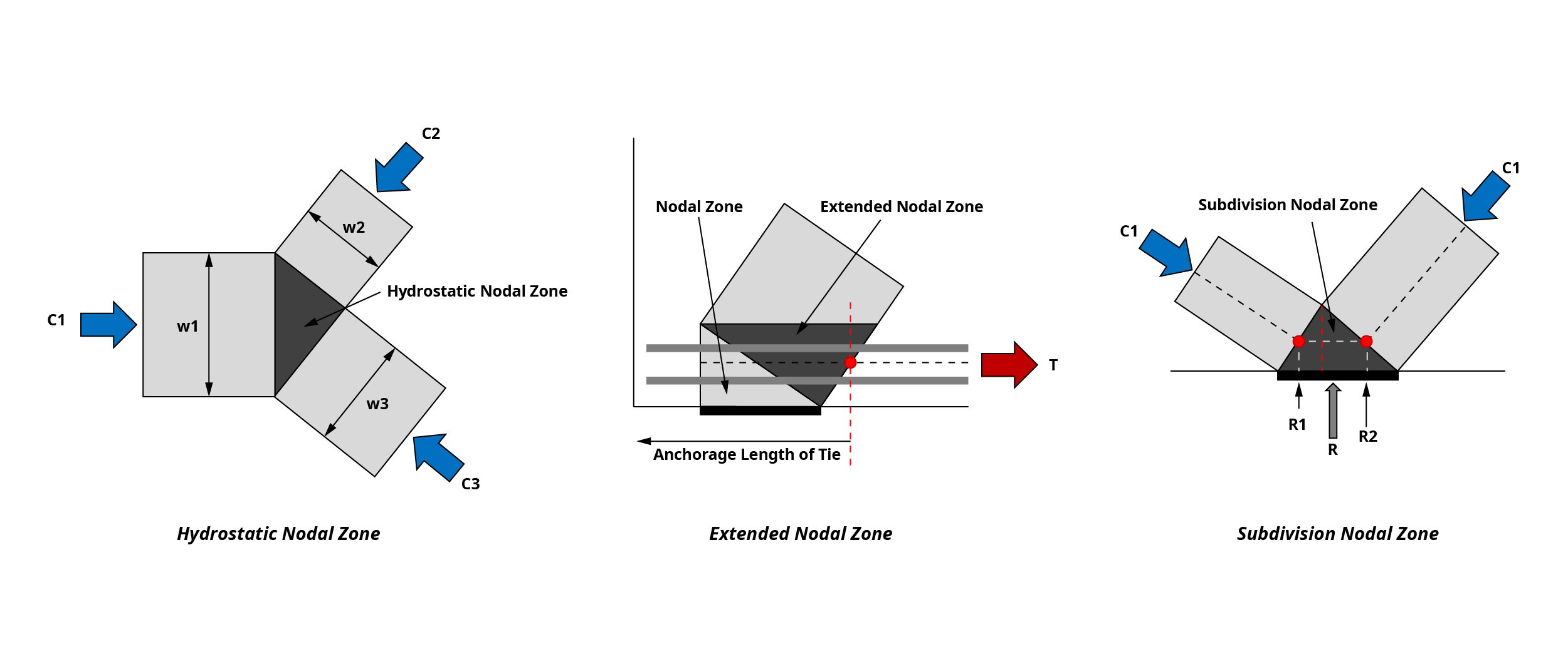 Figure 7: Types of Strut-and-Tie Model Nodal Zones
Part 1 contains only the descriptions of the concepts and roles of each element. The process for calculating the forces acting on each element and calculating the design strength required for design will be described in Part 2.
4. Strut-and-Tie Model Example: 2D Pile Cap
Please look under the DOWNLOAD section below to download the MIDAS BRIDGE "2D Strut-and-Tie Model for 4 Piles Cap Calculator" Excel template. We have provided you with an easy-to-use calculator where you can enter the dimensions of the structure, reinforcement information, and desired code (AASHTO, Eurocode) to design a 2D Strut-and-Tie Model for a 4-pile cap. A detailed explanation of the calculation process and comparison with the results obtained through the 3D Strut-and-Tie model will be looked upon in Part 2.