Get Started midas Civil
 Featured blog of this week

Please fill out the Download Section (Click here) below the Comment Section to download the 3D Strut-and-Tie Model for 4 Piles Cap Calculator
Strut-and-Tie Model
Contents
1. Introduction
2. Determining the Geometry of a Strut and Tie Model
3. 3D Strut and Tie Model - Downloadable Example
4. References
1. Introduction
In Part 1, the basics of the Strut and Tie Model (STM) were covered. In Part 2, we will cover the method of determining STM considering the strut, tie, and nodal zone, and how to calculate the forces required for design. The verification and rebar detailing of the strut, tie, and nodal zone strength for each design standard will be covered in Part 3.
Various design standards in each country not only recommend using the Strut and Tie Model for deep beam design, but also suggest various considerations that must be taken.
- AASHTO LRFD
- 5.6.3 Strut-and-Tie Model
- ACI 318-08
- APPENDIX A – STRUT-AND-TIE MODELS
- Eurocode 1992-1-1
- 6.4 Analysis with strut and tie models
- 5 Design with strut and tie models
- CEB-FIP Model Code 09
- 6.8. DEEP BEAMS AND DISCONTINUITY REGIONS
2. Determining the Geometry of Strut and Tie Model
One of the most difficult factors for engineers when determining the Strut and Tie Model is determining the geometry. There are a lot of things to consider when deciding where and how to place struts and ties, and that’s why a lot of research is still being conducted. In the design standard, it is suggested that struts be placed considering the flow of loads or stresses. Additionally, depending on the strut arrangement method, the load transfer method is expressed with the following terms: arch mechanism, truss mechanism, and combined mechanism. In order to arrange the ties, the details of the reinforcement must be considered. Furthermore, the node, nodal zone, bearing face, etc., must be determined according to the design conditions to obtain the desired calculation results. However, as the shape of the structure becomes more complex, it is very difficult to check the flow of forces and stresses and arrange the struts and ties according to the load transfer mechanism.
The example used in this article is an STM of 4 piles cap as shown in the figure below. We hope this example helps you with your understanding of how to determine the geometry of an STM.
A. Tie
The most important this when determining the location of the tie is that it should be placed at the center of the tensile reinforcement. As stated in Figure 5. “Effective Width of Ties” in Part 1, since the method presented by each design standard is different, it must be checked before deciding the location of the ties.
If the layer of reinforcement increases or the diameter increases due to the increase in the required amount of reinforcement, the center position of the tensile reinforcement changes, and the position of the ties must be changes accordingly. Furthermore, as shown in the figures below, if the position of the tie goes up due to the increase in the required reinforcement, the strut angle becomes smaller, making it unfavorable to the STM, so it is necessary to decide whether to increase the layer of reinforcement or the diameter.
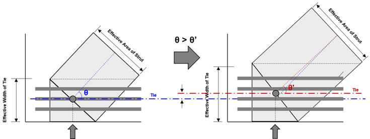 Figure 2: Changes in Effective Width of Tie and Strut Angle according to the increase in tensile reinforcement
B. Strut
The arrangement of struts in STM for 4 piles cap can be determined based on the limit value of the strut angle. When the strut is arranged from the position where the load is applied to the support, and the strut angle is less than the limit value suggested by the design standard, the strut angle can be increased by adding a vertical member.
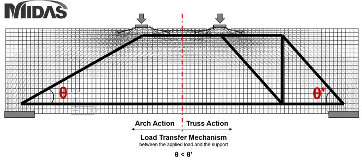 Figure 3: How to arrange struts in STM for Deep Beam design
Calculating the strut angle is not difficult because it can be calculated by knowing the distance from the load acting position to the support, and the height of the STM, but it must be verified because the value suggested is different for various design standards.
- AASHTO LRFD
- 5.6.3.3.3 - Limiting Compressive Stress in Strut
- In AASHTO LRFD, the limit value of the strut angle is not directly specified, but is included in the limit value of the strut compressive stress
- ACI 318M-11
- APPENDIX A – STRUT-AND-TIE MODELS
- arctan(1/2) = 26.5 degrees, rounded to 25 degrees
- Eurocode
- 6.2.3 Members requiring design shear reinforcement
- 1≤ cotθ ≤2.5
- CEB-FIP Model Code 09
- 6.8.2.2 Discontinuity regions
C. Node, Nodal Zone
In the Strut and Tie model, the point where three or more forces gather is called a node, and the simple idealization of the complex stress state in this region is the nodal zone. The nodal zone plays a very important role in STM because it is not only related to transferring the force of struts and ties to other struts and ties, but is also related to anchoring of reinforcement and calculating the effective area of struts.
CCT Nodes
The calculation result of the CCT zone, the area where two compression struts and one tension tie meet, plays a role in determining the settlement length of the tension tie and the effect width of the strut. The calculation method is shown in the figure below.
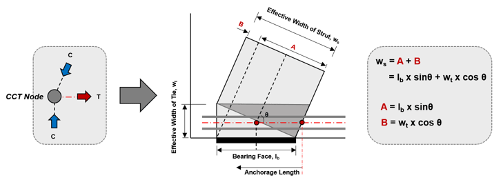 Figure 4: Geometry of CCT Node and calculation of Strut Width
For reference, detailed calculation methods and images of the cross sectional area of the strut in a 3Dimensional STM can be found in References [2], [5], and [8].
CCC Nodes
The figure below shows the comparison between the case where the bearing face is recalculated by distributing the magnitude of the load in the CCC node (where only the compression struts meet) and the case where it is not. When the bearing face is recalculated by applying load distribution, not only the effective area of the strut changes, but also the angle of the strut changes accordingly.
A detailed calculation process and description of the strut width divided into the left and right potions according to the percentage of the applied load can be found in Reference [1].
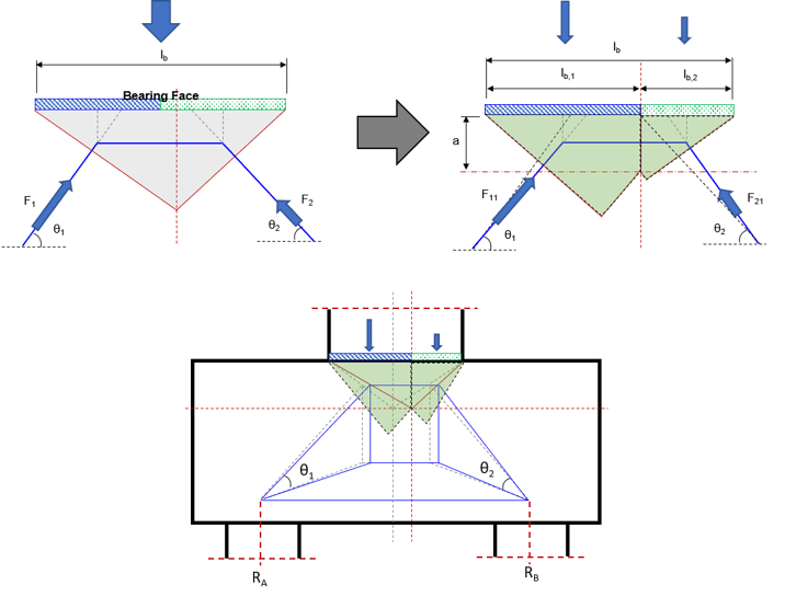 Figure 5: Reconstruction of the Nodal Zone according to the load distribution and the conceptual diagram of the change in the strut
D. Equivalent Force System
Design Example 4 – “Drilled Shaft Footing” in Reference [1] explains how to recalculate the load acting on the Pier bottom as an equivalent load. This is a necessary process not only in 2D STM but also in 3D STM because the location and type of load acting (compressive or tensile forces) varies depending on the load combination (axial, shear force, and moment) to be used in the design. In general, the loading position of the compressive force is determined by the center of gravity of the stress diagram, and the tensile force is determined by the center position of the pier reinforcement. This is because when the force is delivered from the pier to the pile cap, the compression force is transferred through the concrete and the tensile force is transferred through the reinforcement of the pier.
The figure below shows the process of calculating the equivalent force (in US units) through the example in Reference [1] (Figure 4-4 ~ Figure 4-6).
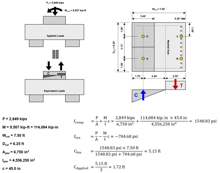 Figure 6: Linear Stress Distribution and Equivalent Force System (FHWA-NHI-130126)
E. Moment Recalculation
In Example 11 – “Deep Pile Cap with Tension Piles” in Reference [3], the pier bottom force is recalculated as the load acting on the STM and used as the design load considering the eccentric distance between the pier bottom and the STM.
The figure below shows the process of recalculating the design force through the example in Reference [3]. (SI units)
In order to obtain the same result value as the example in Reference [3], the MSTM is calculated by rounding the pile head reaction, RB 180.55 kN to 181 kN.
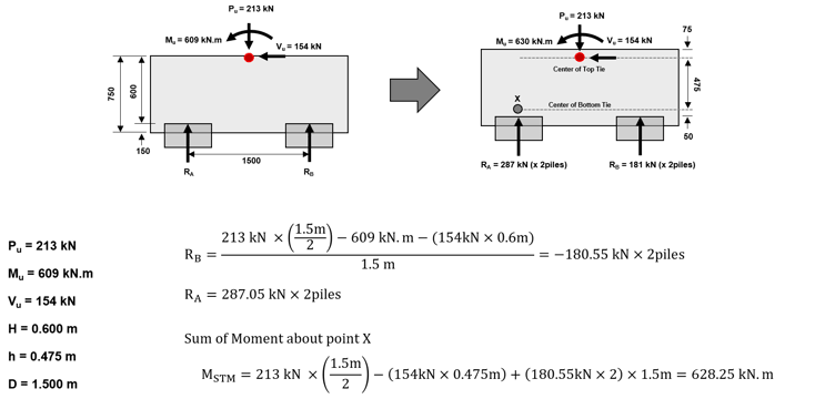 Figure 7: Calculation of the Design Loads acting on the Strut and Tie Model (ACI-ASCE Committee 445, SP-273)
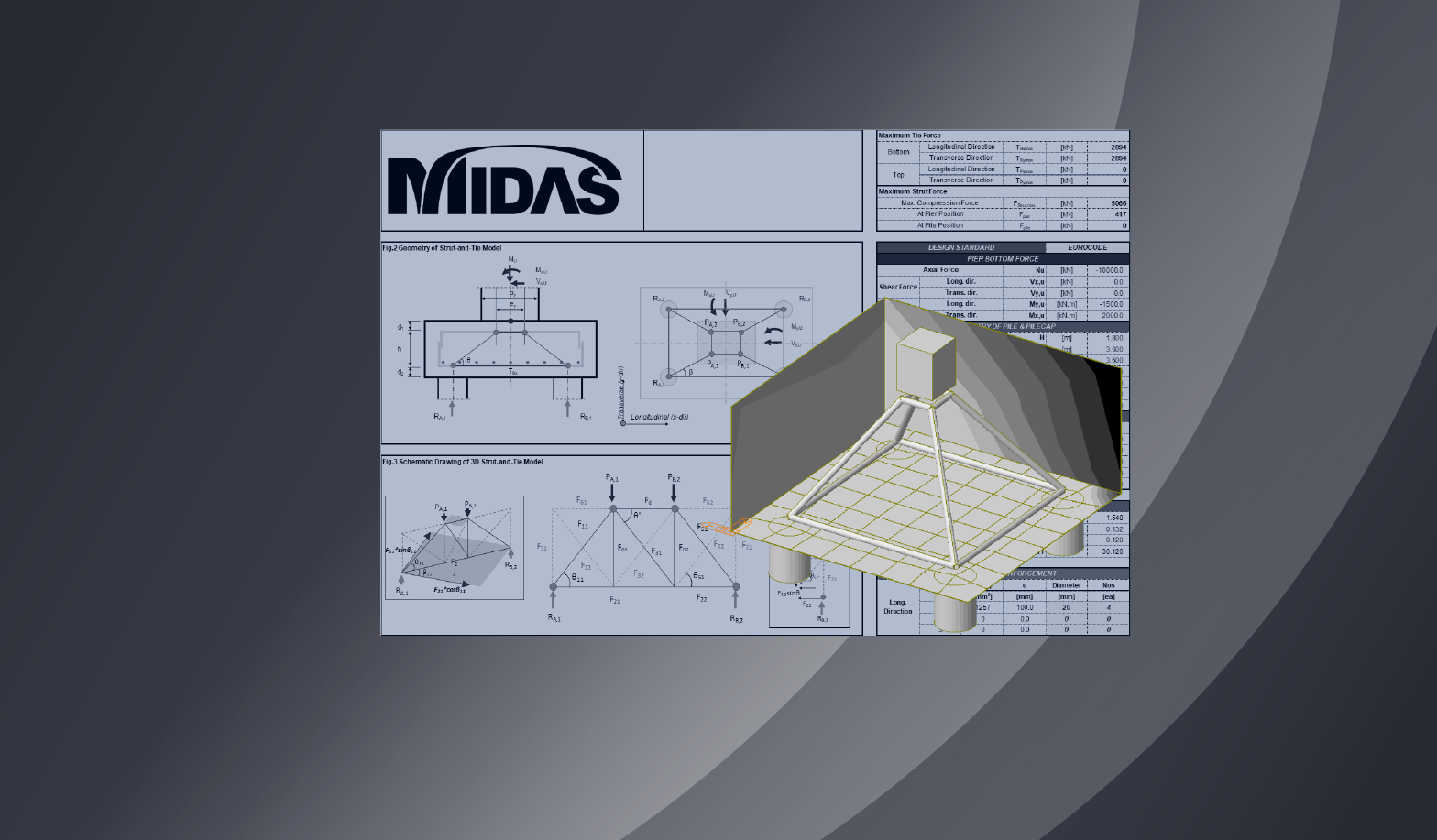
The 3D Strut and Tie Force calculator that can be downloaded below considers all the factors mentioned above except the factors mentioned in D. Equivalent Force System. The process of calculating the Strut and Tie force with 3D STM was constructed based on the ideas obtained from the examples in Reference [3] ACI-ASCE Committee 445, SP-273. Two STM models across the pilecap are constructed and members are placed in any position that can be a strut or tie. Additionally, the necessary members are calculated according to the load combination acting on the STM.
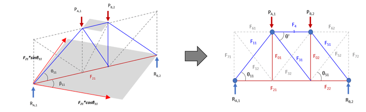 Figure 8: Strut and Tie Model on the downloadable content
As will be mentioned again in the Verification and Rebar Detailing Content (Strut and Tie Model Part 3), the design methods and examples presented in the design criteria are based on experimental 2D design areas and determinate truss calculation methods. Therefore, it is recommended to use a Finite Element Analysis program for STM considering a two-way moment or a load combination that generates a tensile force on a vertical member.
3. Strut and Tie Model Example: 3D Pile Cap
In the Download Section below, we have provided an Excel file that calculates the Strut and Tie force of a 4 Piles Cap with a 3D Strut and Tie Model. Users can enter the dimensions of the structure to be designed as well as the reinforcement information, and select the desired design code (AASHTO, Eurocode). A structural analysis program such as midas Civil must be used for load combinations in which Uplift occurs.
4. References
[1] Federal Highway Administration (FHWA-NHI-17-071), Strut-and-Tie Modeling (STM) for Concrete Structures
[2] ACI-ASCE Committee 445 (2002), Examples for the Design of Structural Concrete with Strut-and-Tie Models; SP-208
[3] ACI-ASCE Committee 445 (2002), Further Examples for the Design of Structural Concrete with Strut-and-Tie Models; SP-273
[4] American Concrete Institute (ACI 318-14), Building Code Requirements for Structural Concrete
[5] American Association of State Highway and Transportation Officials, AASHTO LRFD Bridge Design Specifications
[6] Comite Euro-International du Beton, CEB-FIP Model Code 1990
[7] Yun, Y. M. and Ramirez, J. A. (2016) Strength of Concrete Struts om Three-Dimensional Strut-and-Tie Models
[8] Yun, Y. M. and Ramirez, J. A. (2019) A Three-Dimensional Strut-and-Tie Model for a Four-Pile Reinforced Concrete Cap
[9] Eurocode 2, Design of Concrete Structures, Part 1 : General Rules and Rules for Buildings