Get Started midas Civil
 Featured blog of this week

Please fill out the Download Section (Click here) below the Comment Section to download the Project Application
Background
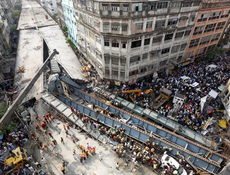
In 2016, Kolkata witnessed a major steel bridge failure of the Vivekananda Road Flyover during construction which led to 27 deaths and 50 injured. The construction work of a 2.2km flyover began in 2009 and was expected to be completed in 2010. Although six years behind schedule, it was not yet completed the erection part till 2016 (Figure 1).
Was it poor construction?
As per the researchers and study, the main longitudinal girders spanning between the hammerhead piers and without any transverse bracing on the compression flanges to prevent the lateral-torsional buckling, which imposed additional horizontal loads on steel box girders.
Potential causes
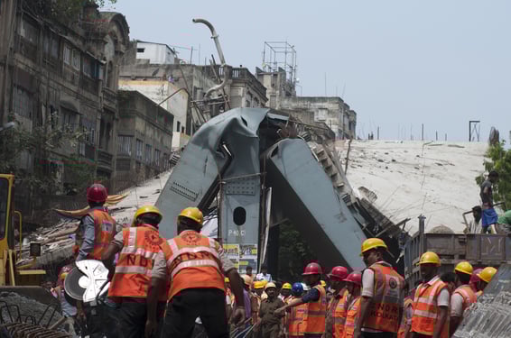
From Figure 2, one can see the plate girder’s top flanges were not supported by temporary bracings, resulting in the long plate girder to fail in lateral-torsional buckling. The two major reasons that led to the collapse of the Vivekanada Road Flyover are the gaping design and engineering flaws. After analyzing the disaster, reports said the structure was under severe stress at the instant the girders were positioned on the nearby piers. The stress was pushed beyond tolerance level when the concrete deck was cast, aggravating the crisis.
Inadequate Bracing
Only horizontal bracing was present in girders. Lack of vertical bracing caused unrestrained compression of the girder flange. These horizontal and vertical bracing would have restrained compression of girder flanges, preventing skewing and lateral-torsional buckling.
How pier 40 collapsed?
The sequence of failure is shown in figure 3.
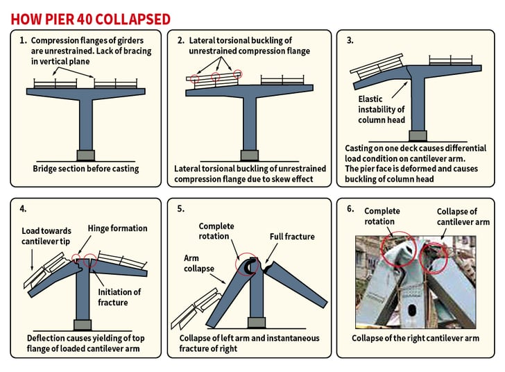 Figure 3: Sequence of the collapse of the cantilever arm of pier 40
Technical aspect
As the Kali Krishna Tagore Street cuts across diagonally, the span crossing over Rabindra Sarani had to be skewed. In addition to the load added on top of the “I” shaped girders, this mild skewing of the span caused a lateral torsion effect. To reduce the torsion or twisting effect and keep the girders in shape, they needed to be properly restrained. There was no vertical bracing to restrain the flanges. The instability caused by this led to a massive strain on the structure and loosened girder bolts.
It was not a surprise that the failure had occurred even when the bridge was not subjected to any live loads from moving vehicles. The bracings on the compression flanges to prevent lateral buckling were absent on the longitudinal beams spanning between the hammerhead portal frames. This issue also imposed additional horizontal loads on the girders. It is clear from the failure pattern of the top flange plates of the portal frame “I” girders that the rupture and eventual failure were caused due to internal defects inside the plates. These inbuild residual stresses tend to lower the yield stress level, and these catastrophic failures are bound to occur when loads come on them, in the absence of such practice of not providing support systems.
Things to be done to prevent such failures?
In the case of steel composite girders, it is necessary to perform buckling analysis of girders only. For girders with transverse bracings, it is important to check for lateral-torsional buckling and critical buckling load.
For this, we have made a sample test model with different cases.
- Girders with no transverse restrains
- Girders with Horizontal restrains
- Girder with vertical as well as horizontal restraints
A simply supported girder with a 30m span has a typical girder depth of 2m. The load at the time of slab casting, i.e., wet concrete as pressure (39.06kN/m2) along with girder weight, is applied to carry out the buckling analysis. The buckling mode shapes at each case shown in figure 4 to figure 9.
.jpg?width=726&name=Buckling%20mode%20shape%20for%20girder%20only%20case%20(mode%201).jpg) Figure 4: Buckling mode shape for girder only case (mode1)
Figure 4: Buckling mode shape for girder only case (mode1).jpg?width=784&name=Buckling%20mode%20shape%20for%20girder%20only%20case%20(mode10).jpg) Figure 5: Buckling mode shape for girder only case (mode10)
Figure 5: Buckling mode shape for girder only case (mode10)
.jpg?width=785&name=Buckling%20mode%20shape%20for%20girders%20with%20horizontal%20bracing%20case%20(mode%201).jpg) Figure 6: Buckling mode shape for girder with horizontal bracing case (mode 1)
Figure 6: Buckling mode shape for girder with horizontal bracing case (mode 1)
.jpg?width=784&name=Buckling%20mode%20shape%20for%20girder%20with%20horizontal%20bracing%20case%20(mode%2010).jpg) Figure 7: Buckling mode shape for girder with horizontal bracing case (mode 10)
Figure 7: Buckling mode shape for girder with horizontal bracing case (mode 10)
.jpg?width=785&name=Buckling%20mode%20shape%20for%20girder%20with%20horizontal%20and%20vertical%20bracing%20case%20(mode%201).jpg) Figure 8: Buckling mode shape for girder with horizontal and vertical bracing case (mode 1)
Figure 8: Buckling mode shape for girder with horizontal and vertical bracing case (mode 1)
.jpg?width=784&name=Buckling%20mode%20shape%20for%20girder%20with%20horizontal%20and%20vertical%20bracing%20case%20(mode%2010).jpg) Figure 9: Buckling mode shape for girder with horizontal and vertical bracing case (mode 10)
Figure 9: Buckling mode shape for girder with horizontal and vertical bracing case (mode 10)
From the results, it can be concluded that as per the transverse restrains, i.e., bracings, the transverse rigidity to the main longitudinal girders will increase, further amplifying the buckling capacity.
The results are tabulated in Table 1 below.
.png?width=634&name=image%20(11).png) Table 1: Buckling loads for test cases
Table 1: Buckling loads for test cases
A significant amount of buckling modes on the web is expected because buckling analysis, which is a linear eigenvalue analysis, occurs at the weakest point, usually at the thin plates or webs. In the case of braced main girders, web buckling will occur before the main girders experience any global buckling.
Unfortunately, there is no easy way to find the global modes. However, some methods can be used to narrow the search down. The web of the girders in the out-of-plane can be artificially stiffened while the in-plane behavior is left as it is. This will increase the critical load significantly for the web's local buckling modes, while the global buckling of the main girders will not be substantially affected as the out-of-plane bending of the web does not govern it.
Summary
In summary, it was mandated for the contractor to provide some temporary formwork, offering some bracing action to get transverse rigidity to the main girders before placing the concrete over the girders. The collapse took place after about 10 -12 hours of concrete placement. By this time, the initial setting of concrete would have taken place, giving strength to concrete, in turn, lateral restraint to the girder subjected to deadflyover load only. Also, from the pictures, shear connectors seem to be provided on top of the girders. This viewpoint brings the question of whether the collapse was due to twisting moments caused by inherent unequal loading on the girders, as well as the lack of torsional restraint at supports by means of web cleats or end plates.
Bad engineering /detailing of the skewed /curved portion of the bridge is an evident reason for the collapse. The Mild Steel girders were used to support the green concrete poured in the deck slab. The design may have considered the slab itself to be a lateral restraint to resist horizontal forces. However, in its steel with green concrete, any lateral restraint is not to be expected. In this condition, lack of cross-beam design, lack of connections with the main girders, absence of shear connectors between the steel girder and deck slab, and no presence of arrestors to prevent the longitudinal girders from unseating from their bearings, lead the girders to crash down, failing about their minor axes. So, suppose the Buckling Assessment had done before the erection to know the effect of lateral torsion. In that case, it could have prevented the Steel Bridge Flyover Collapse during the erection stage itself.


/Photos%20of%20specialists/Pratap-1.png)


/2020%20Pics%20for%20drafts/Traffic%20Load%20Consideration%20to%20Different%20Types%20of%20Bridges%201-1.jpeg)
/Load%20Rating%20of%20Steel%20U-Through%20Bridge/Load%20Rating%20of%20Steel%20U-Through%20Bridge%20345%20240.png)