 Get Started midas Civil
 Featured blog of this week

Please fill out the Download Section (Click here) below the Comment Section to download the Full Webinar PDF File.
Knowing about the analysis of cable-arch bridges with seismic dampers is important because it helps ensure the safety and reliability of these structures during seismic events.
The webinar will highlight how Midas was used to the design of the new structure. It will also cover points including how construction sequence was considered, and some aspects regarding the seismic behavior.
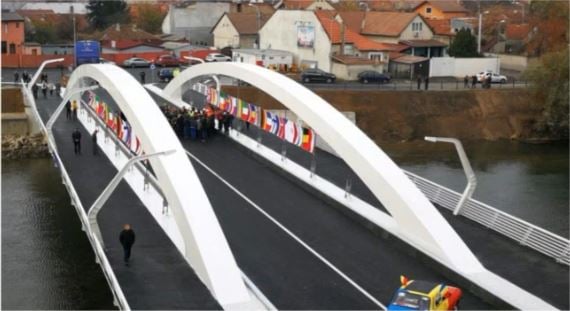
The Centennial Bridge in the city of Oradea, Romania was commissioned by Oradea City Hall to a joint venture formed of FreyRom SA & Procons SA and was designed by Integrated Road Solutions SRL in 2017-2018. The bridge was built during 2018 and was opened to traffic on 1st of December 2018, to mark the 100 years since the country was united. The bridge is an arch having a span of approximately 80m and supports a two lanes carriageway and also 2 footways with a width of 3m each.
Key Points
1: Construction sequence for bridge
Abutments, deck installation and the cables installation are constructed in a sequence, with the results taking into account accumulated dead loads. In this part we will see how the model was realised following the entire technological process of construction.
2: Seismic Analysis
Initially the bridge statical scheme proposed in the feasibility study has been a restrained arch at both ends. However, during the design, it was observed that the fundamental period of the bridge was practically the same with corner period of the local area. Even if the area in which the bridge is constructed is one of the less dangerous in the country, having these two periods so close is not something desirable. In this part of the presentation we will see how the fundamental period of the bridge was changed and how the usage of dampers helped in achieving the desired result.
3: Design Reports
We will see here how Midas Civil can help you with the design of various elements of the structure.
Table of Contents
*Click the content to move to the section
1. Overview of the Project
2. Overview of the Bridge Model in midas Civil
3. Construction Stage Analysis
4. Time Dependent Material
5. Seismic Issues
6. Buckling Analysis
7. View of the Finalized Bridge
Overview of the Project
The project shared in the webinar is a bridge which is located in the western part of the country in the city of Oradea. It crosses the river Crisul Repede with a single span of around 73.5m. The bridge is a double restrained arch having the carriageway located in the middle of the arch. The type of this bridge is a half-through arch bridge. The deck of the arch bridge is supported by 8 stay cables. Each of the stay cables has a different inclination. It was planned in terms of the aesthetic view. The cables together with the arch and deck make the image of a royal crown. The shape of the crown is meant to mark the 100 years from the unification of the three main Romanian provinces.
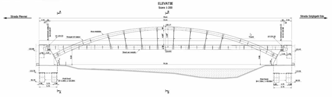
Fig. The Elevation View of Example Bridge
The superstructure of the bridge carries two lanes for cars and two footways of 3m each. The footways are located at the exterior of the carriageway. The superstructure is formed by two closed steel boxes connected together by cross-beams at each 2.475m. The carriageway is supported on a reinforced concrete slab which is connected to the crossbeams only to avoid the tensile force on the RC slab. The tensile force happens on the main beams of arches. It is a structural character of the arch. In order to provide for the lateral stability of the bridge, the section of arches is varying from 1.2m x 1.3m to 1.6m x 0.9m.
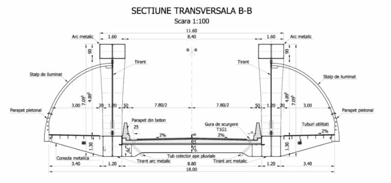
Fig. Cross-section View
The substructure of the bridge is composed of two abutments on drilled piles with a diameter of 1.5m.
Overview of the Bridge Model in midas Civil
The bridge model is modelled in midas Civil. The piles, frames of arches, and cross-beams are modelled by beam elements. The abutments are modeled by solid elements to obtain detailed results at the abutments. The stay-cables are modelled by truss elements. It was assumed that the effect of cable elements is less because the shape of stay-cables is straight in the vertical direction.
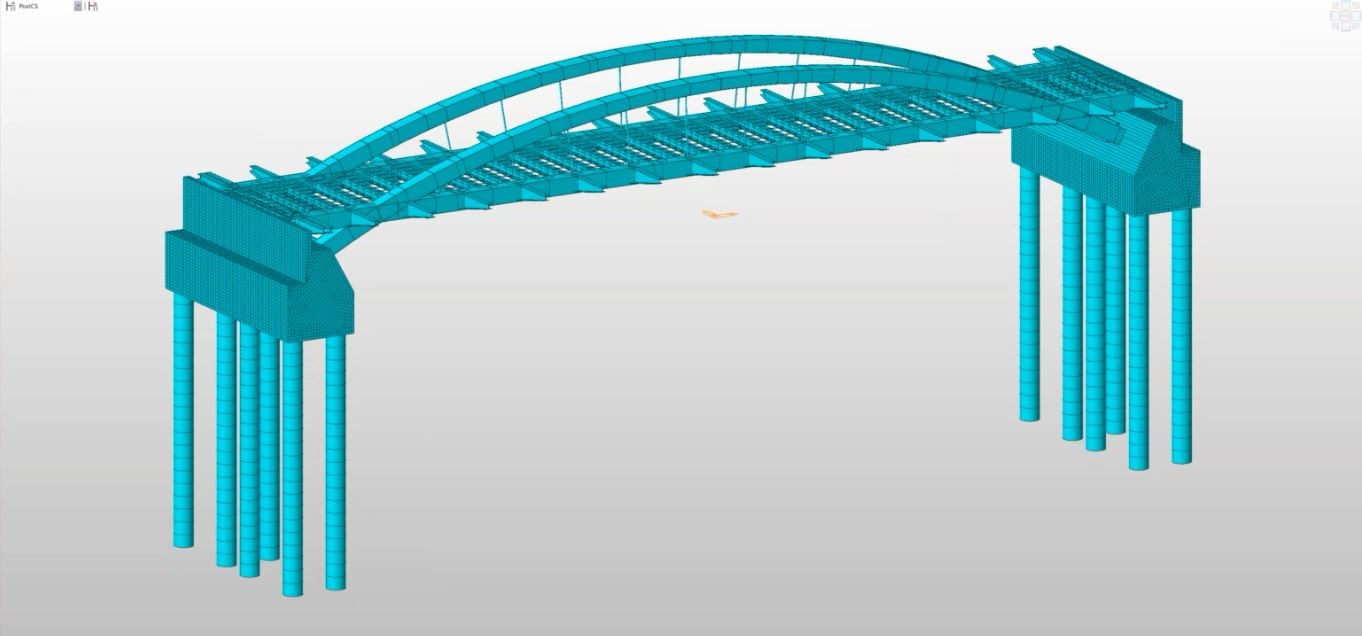
Fig. Bridge Model in midas Civil
Construction Stage Analysis
As with any structures, it is important to take into consideration the way the structure is built.
1. Installation of steel elements of the structure on intermediate supports and abutments.
Articulation points of the bridge are on the arches and main beams. The length of each part is not the same. Articulation points are depending on various reasons. Particularly, the transportation plan was considered. Articulation points were modelled by using Point spring function in midas Civil. At the first stage of construction, the segments of main beams and arches are not continuous over the intermediate supports. These are not capable to withstand bending moments until the structure is fully connected. Therefore, Beam end release function in midas Civil is applied to avoid the bending moments at the articulation points.
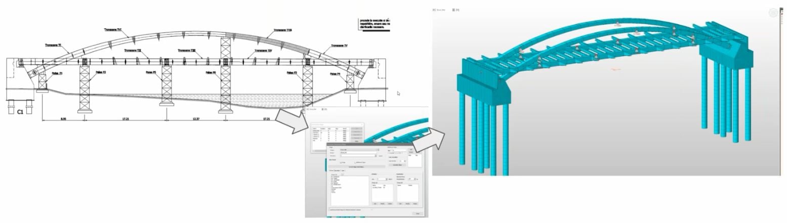
Fig. 1st Step of Construction
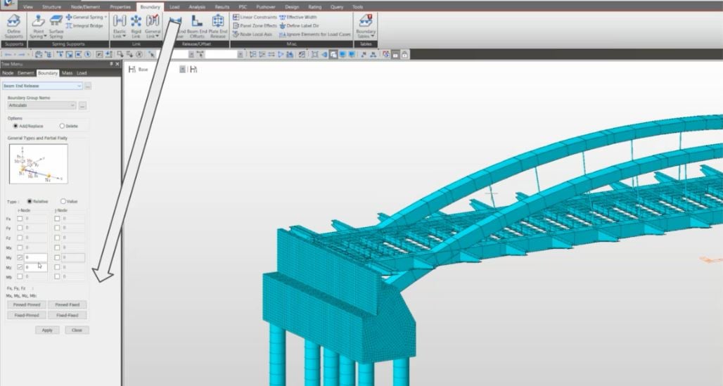
Fig. Beam End Release function
2. Loading of the weight of in situ concrete for the deck
After step no.1, The deck is constructed via in situ concrete method. The weight of curing concrete is considered using static loads during the form work. In this model, composite section type is applied to beam elements for the cross beams. Actually, the deck is connected onto cross beams because the main beams of arch bridge have the tensile force because of a structural character of arch bridges. In order to consider the construction sequences, Composite Section for Construction Stage function is applied.
3. Activation of the full section of the cross beams
After step no.2, the static load for curing concrete is deactivated. At the same time, the whole section of cross beam is activated to consider all stiffness of the section.
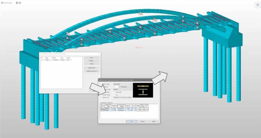
Fig. Composite Section for Construction Stages function
4. Activation of the stay cables
After step no.3, the stay cables are activated. The stay cables are not tensioned separately like cables in a cable-stayed bridge. The optimization is not very big part. Therefore, tensioning work started to each of them.
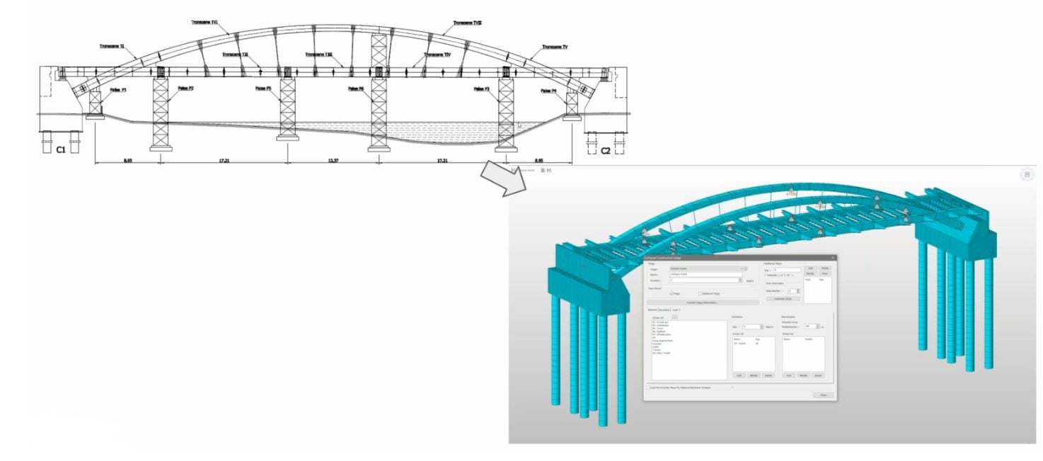
Fig. Activation of Stay cables
5. Removal of the intermediate supports and temporary hinges
After step no.4, boundary conditions for temporary supports are deactivated.
Time Dependent Material
While construction stage analysis is conducted, the time dependent material for concrete is applied by Time Dependent Material function in midas Civil. The slab is constructed via the in situ concrete therefore, the effect of time should be checked.
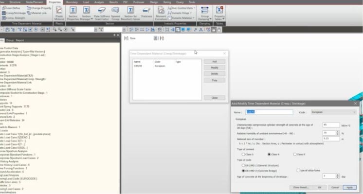
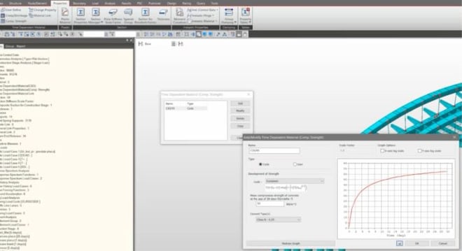
Fig. Time Dependent Material function
Seismic Issues
The bridge is not located in a high seismic area with ag=0.15g, and Tc=0.7sec. In order to check the effect of the seismic, Response Spectrum function is applied. However, this kind of bridges is rather stiffness being normally restrained at both ends and during the analysis. It was observed that the fundamental period of vibration of the bridge almost matches with the corner period (Tc). T=0.709s ≒ Tc =0.7s, and by this effect, although the danger of a significant earthquake in the area is small, the effect of resonance could amplify the seismic response.
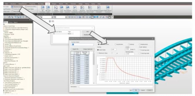
Fig. Response Spectrum function
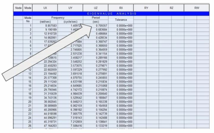
Fig. The result of Eigenvalue Analysis
As the general appearance of the bridge, design could not be changed. Being already approved from the previous design stage an other solution needed to be found in order to minimise the influence of the earthquake in the behavior of the bridge. The solution was to release the bridge in the transversal direction during the seismic event. And while keeping it in fixed position during normal service. This behaviour was achevied using a PDS isolator on both abutments of the bridge.
midas Civil offers three types of dampers to be used into the desing with three behaviour laws as follows:
- Maxwell Model
- Kelvin (Voigt) Model
- Combined Maxwell - Kelvin Model
For this project, The Kelvin Model was used. And the parameters used in calculation have been discussed and agreed with dampers supplier. In order to minimise the cost of the production and the speed of delivery and at the same time achieving the desired effect of increasing the vibration period.
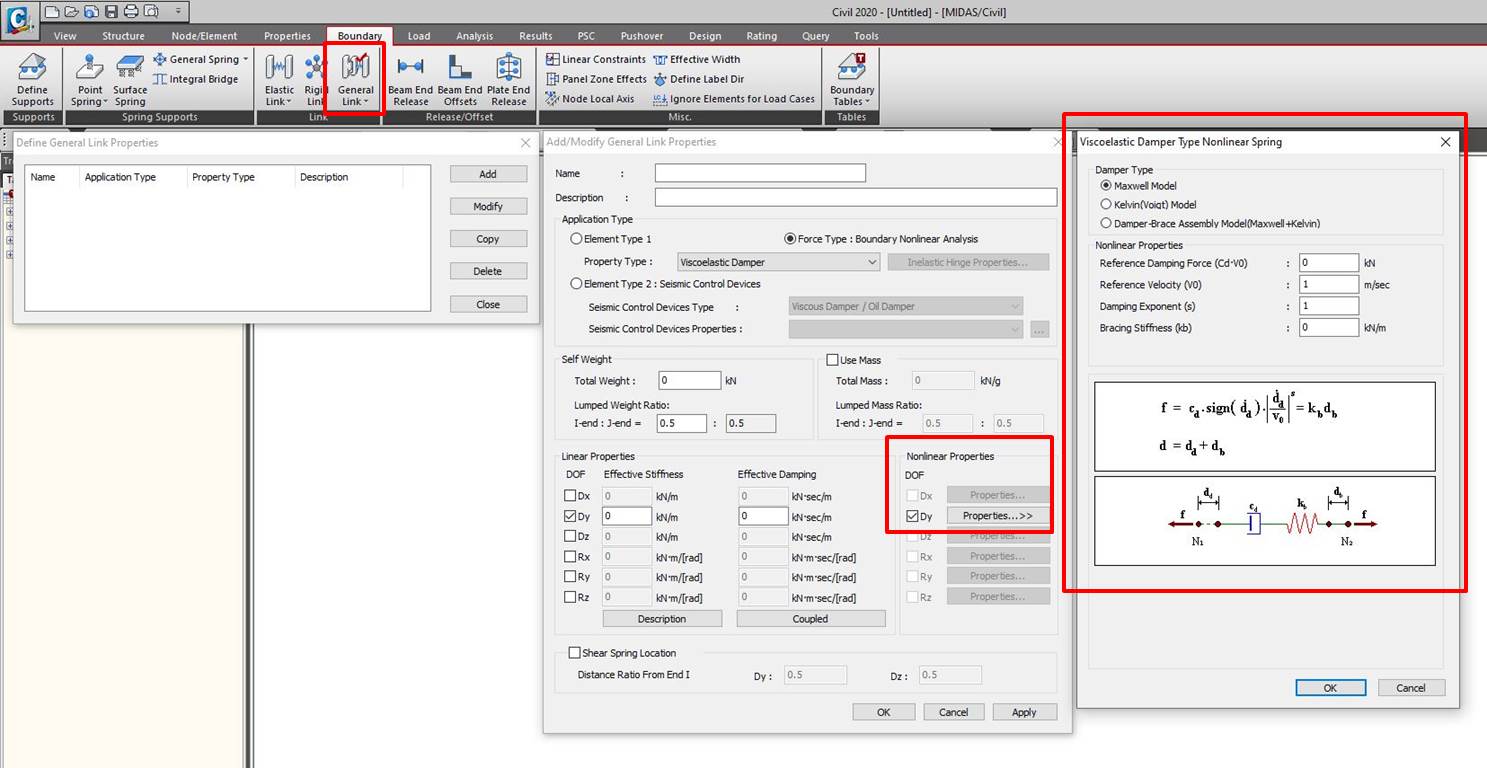
Fig. General Link property & Nonlinear Properties for Damper
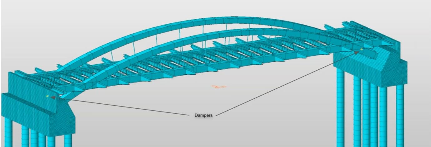
Fig. Dampers in Model View
After running the model, the fundamental period of vibration of the bridge has increased from 0.7s to 2.83s.
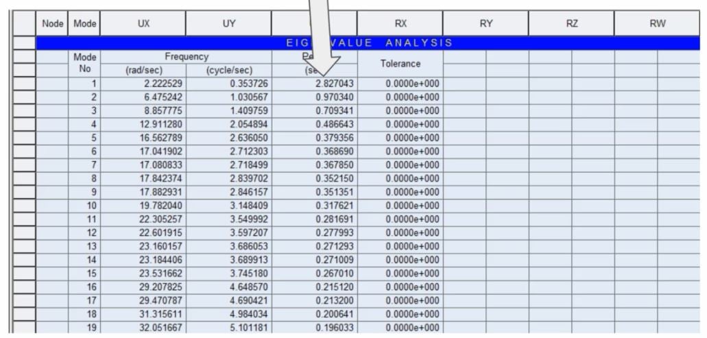
Fig. The result of Eigenvalue Analysis considering dampers
Practical implementation of the damper has been made by connecting the PDS to a cross beam and to the abutment. At the same time, during the seismic event, it is necessary to let the bridge slide in the transversal direction so a separate detail needed to be put in place so that during normal service, the bridge should act as fuly restrained and during the earthquake, the displacement in the transversal direction should be allowed. The solution identified was to restrain the arches at the connection with two steel elements placed one at the top and one at the bottom of the arch. The arch itself is sliding onto a teflon plate in case of a seismic event. During normal service, the structure shall be kept safe in position by the PDS device.
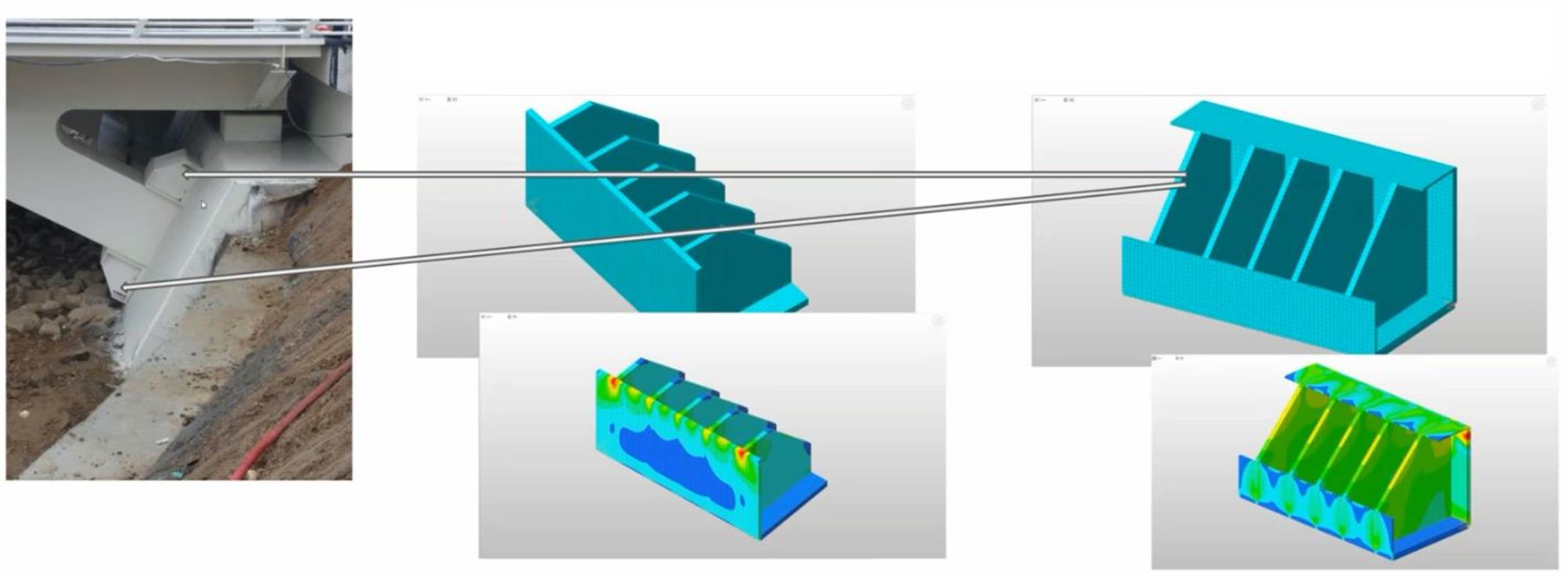
Fig. PDS devices
Buckling Analysis
The buckling analysis is conducted because the main part of the bridge is made by steels. A separate model should be created for the buckling analysis because this analysis can't be made simultaneously with Settlement, Time History or Moving Load analysis. The procedure in midas Civil to evaluate the buckling is the following:
1. Select Analysis -> Buckling.
2. Select the number of buckling modes to be analysed.
3. Select the loads to be considered. Two types are available.
a. Constant loads: Dead loads
b. Variable loads
4. Run Analysis.
After the analysis is completed, check the buckling mode shape. It can be found in the path(Results > Buckling Mode Shapes or Results > Results Tables > Buckling Mode Shape). In order to get the eigenvalues which for this analysis is actually the critical load factor with which the variable load should be multiplied in order to get the buckling in the structure.
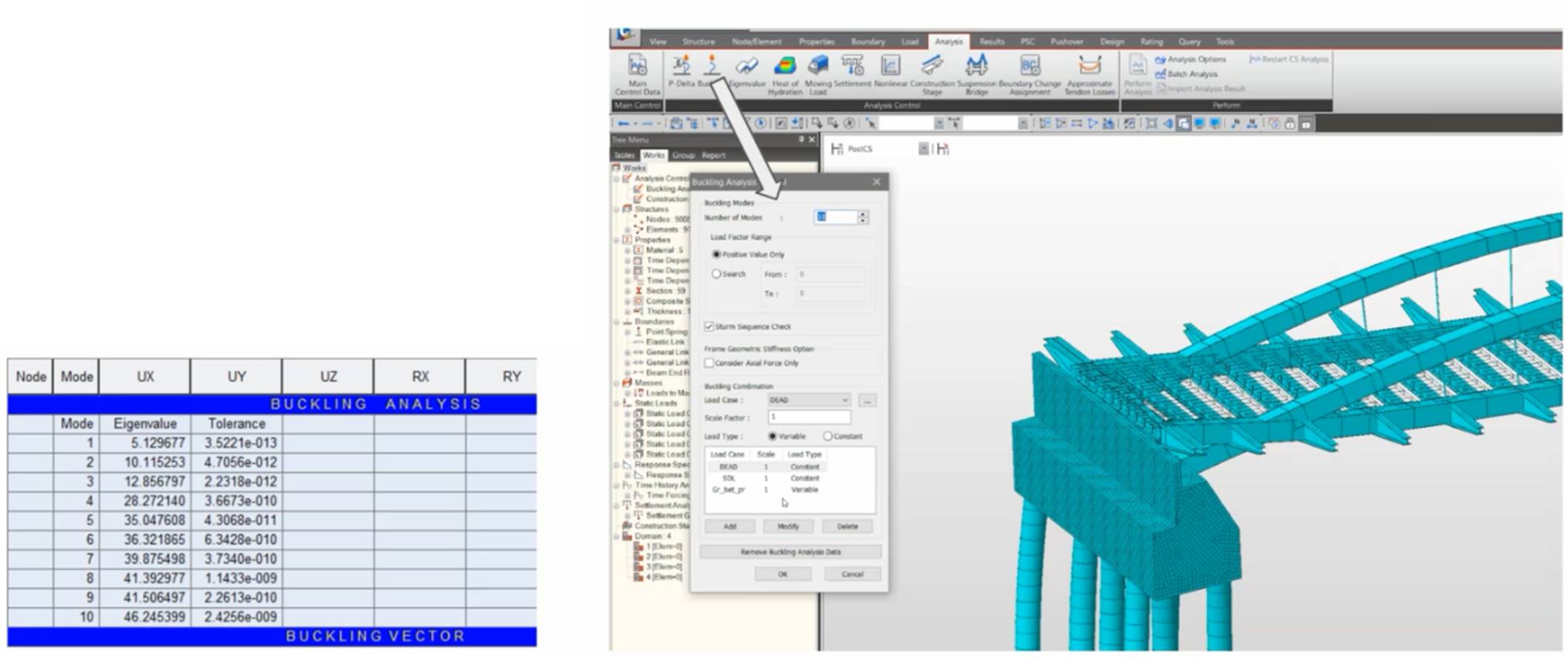
Fig. Buckling Analysis & Results
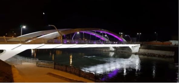
View of the Finalized Bridge


/Cable-arch%20bridge%20analysis%20with%20seismic%20damper/12_Cable-arch%20Bridge%20Analysis%20with%20Seismic%20Damper.jpg)

/345%20240/Structural%20analysis%20of%20Incrementally%20Launched%20bridge.png)
/Static%20Analysis%20of%20Cable-Stayed%20Bridges/Static%20Analysis%20of%20Cable-Stayed%20Bridges%20345%20240.png)