Get Started midas Civil
 Featured blog of this week

Please fill out the Download Section (Click here) below the Comment Section to download the Webinar Presentation.
Watch the Full Webinar Video
In the design of bridges, it is often unreasonable and impractical to design elements to resist strong seismic movements elastically. Thus, it is common in Seismic Design Methodologies to permit ductile yielding of elements to reduce the overall forces resisted by the bridge.
The webinar highlights the importance of plastic hinges in bridge seismic design. It also introduces Pushover Analysis (PA), which is continuously gaining popularity over the last few years.
Key Points
1. Why is Pushover Analysis needed in the analysis of bridges?
Pushover analysis is a nonlinear static analysis method that accounts for the redistribution of actions as the bridge behaves inelastically. This method provides a better approximation of the bridge's behavior than available elastic analysis methods.
2. Importance of Plastic Hinges on bridges
Plastic hinges are primarily energy dispersing elements that occur in the event of a strong earthquake. The economic savings and design protection to other elements due to plastic hinges highly outweigh the cons of dealing with repairable damages.
3. Pushover Analysis using midas Civil
During the 'Learn the basics of Pushover Analysis using MIDAS Civil' session, the speaker shows how to set up the model, define hinges, pushover procedures, and interpret results.
What are Plastic Hinges?
.png?width=548&name=Ductile%20Substructure%20and%20Elastic%20Superstructures%20system%20allowing%20Plastic%20Hinges%20(US%20DOT%20FHWA%202014).png) Figure 1. Ductile Substructure and Elastic Superstructure system allowing Plastic Hinges (US DOT FHWA 2014)[1]
Figure 1. Ductile Substructure and Elastic Superstructure system allowing Plastic Hinges (US DOT FHWA 2014)[1]
A plastic hinge is a section of an element where plastic bending occurs. Plastic hinges are developed when a section has exceeded its elastic capacity and has entered plastic behavior. It should be noted that they are NOT true hinges and will continue to have lateral resistance up to a certain point.
To better understand plastic hinges, consider the simple single-degree-of-freedom (SDOF) structure below, with an expected hinge at the column base:
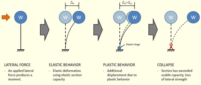 Figure 2. Simple SDOF structure with applied lateral force
The plastic hinge forms after a section reach yield capacity and will be able to accommodate increased displacements under plastic behavior, which can be a considerable amount just before the collapse.
Purpose of Plastic Hinges
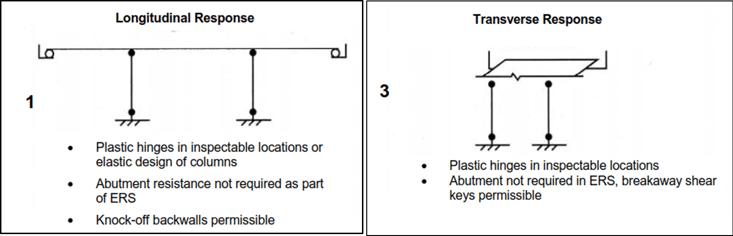 Figure 3.Allowable Earthquake-Resisting System (ERS) employing a Ductile Substructure with an Elastic Superstructure (AASHTO Guide Specification for LRFD Seismic Bridge Design)[2]
Plastic hinges are commonly considered energy-damping devices that allow increased displacement of the bridge via plastic rotation. It is permitted in various design codes, including those using the traditional Force-Based method of design.
The formation of the hinges allows plastic deformation, which in turn reduces the peak elastic seismic design force needed to be resisted by the bridge.
Although plastic hinge formation causes irreversible deformations, they are only allowed for strong seismic events with a low probability of exceedance.
Pushover Analysis
Pushover analysis is a technique in which a structure is subjected to incremental loads controlling either forces or displacements. It is a nonlinear static method of analysis that uses explicit nonlinear methods to assess the structure's capacity. It also approximates the sequence of cracks, yielding, and plastic hinge formation of the structure.
The analysis of the structure via pushover analysis assumes that structures oscillate predominantly in the lower modes of vibrations during seismic events, which reduces a multi-degree of freedom system (MDOF) to an equivalent single-degree-of-freedom system (ESDOF).
To better help in understanding the concept of pushover analysis, consider an SDOF system with an incrementally increased lateral force.
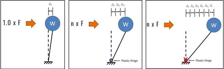 Figure 4. Simple SDOF structure with applied incrementally increasing lateral forces
Incrementally increasing the lateral force causes the structure to undergo the following stages:
- Force is initially applied, and structure behaves elastically.
- Force is multiplied by a factor of ‘n’ wherein the base of the column reaches yield capacity, and a plastic hinge is formed.
- The unchanged force multiplied by ‘n’ produces additional displacements until the loss of lateral strength of the plastic hinge is achieved.
The pushover analysis records these stages, and a corresponding pushover curve is produced.
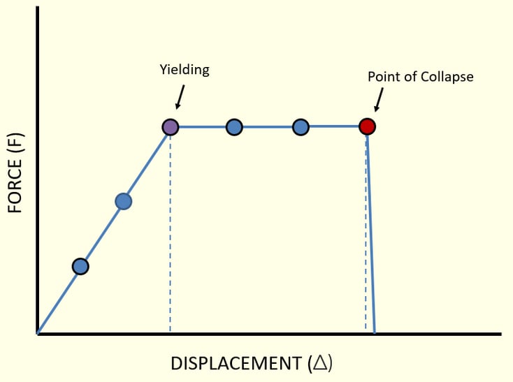
Figure 5. Pushover curve from the SDOF system
Pushover analysis is used as a tool in two commonly known nonlinear static design methods: (1) direct pushover method and (2) iterative capacity/demand spectrum method.
For the more straightforward direct pushover method, the procedure can be summarized as below:
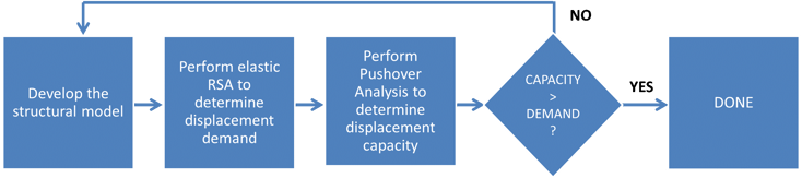 Figure 6. Summarized procedure for the direct pushover method
Pushover Analysis using midas Civil
Midas Civil is capable of all analysis and investigations to carry out a pushover analysis of a bridge properly. As an introductory guide, consider the following steps:
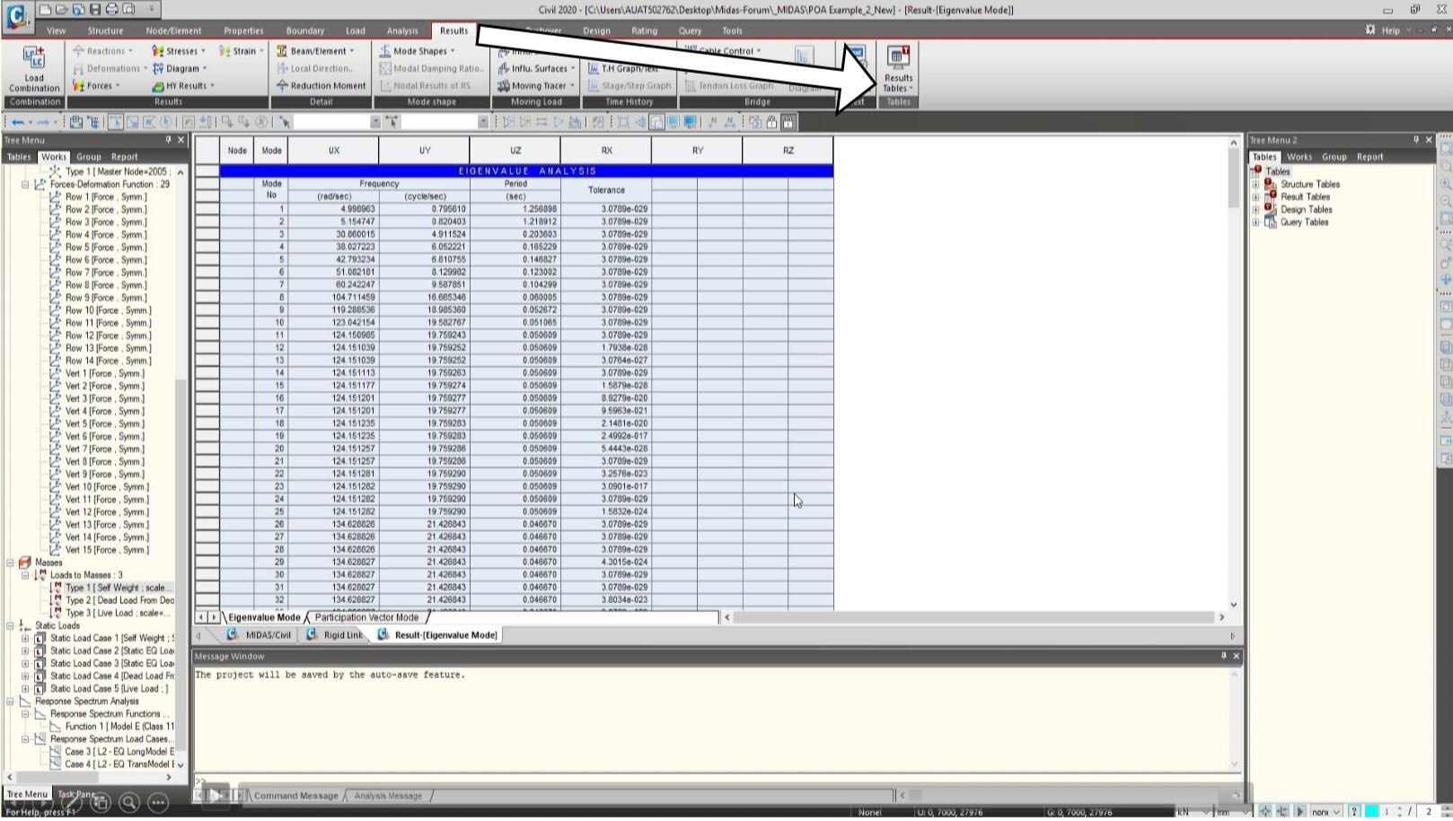
1. Verifying results of the Response Spectrum Analysis (RSA)
It is important to check the results of the RSA analysis if the behavior of the bridge has been properly identified. The check is normally done by verifying that the cumulative mass participation is at least 90%. The governing period of the structure should be noted because this value is checked versus project and code requirements.
The results can be seen via Results Tab -> Results Tables -> Vibration Mode Shape.
2. Defining Pushover Global Control
The Pushover Global Control window in midas Civil allows us to define various general settings for the pushover analysis.
It is accessed via Pushover Tab -> Global Control.
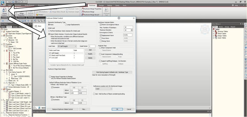 Figure 8. Pushover control window
3. Defining Pushover Load Cases
Load Cases are defined via the Pushover Tab -> Load Case.
The load case can either be Load Controlled or Displacement Controlled. The Load Patterns for the pushover analysis are also defined in this window.
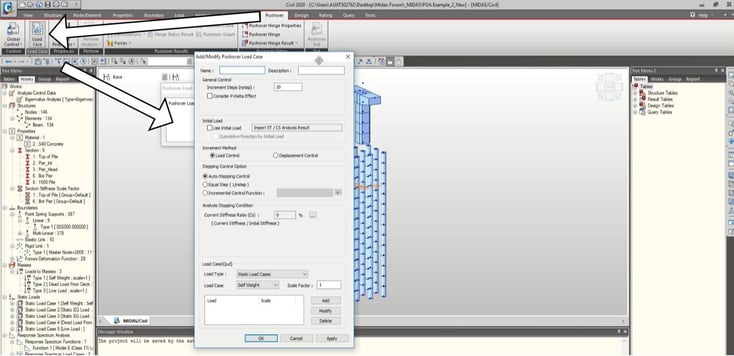 Figure 9. Pushover load case window
4. Defining Hinges
The definition of the Hinges can either be manually assigned via Pushover Tab -> Hinge Properties -> Define Hinge Properties or via the General Section Designer.
The webinar focuses on using the General Section Designer, which can be accessed via the Tools Tab -> General Section Designer.
The General Section Designer allows us to define sections (steel, concrete, composite) and their corresponding inelastic properties. Various Hysteresis models are defined in the program by default, requiring inputs determined from the relevant design code.
%20-%20Section%20Definition.png?width=734&name=midas%20General%20Section%20Designer%20(GSD)%20-%20Section%20Definition.png) Figure 10. midas General Section Designer - Section Definition
Figure 10. midas General Section Designer - Section Definition
After definitions of the section are considered, a moment-curvature (M-Phi) analysis can be performed. The analysis results are presented with various data points, which can be exported into an external report. More importantly, the results of the M-Phi analysis can then be exported into midas Civil.
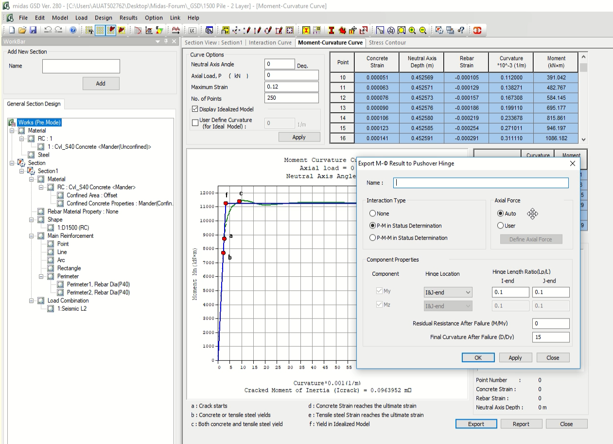 Figure 11. midas General Section Designer - M-Phi analysis
5. Interpreting Results
After assigning the hinges and performing the Pushover Analysis via Pushover Tab -> Perform Analysis, Reactions, Deformations, Forces, and Hinge Status can be seen under the Pushover Tab.
Each step in your pushover analysis has corresponding results. If you aim for a specific step, such as the first yield, you can move through all results via the Tree Menu window.
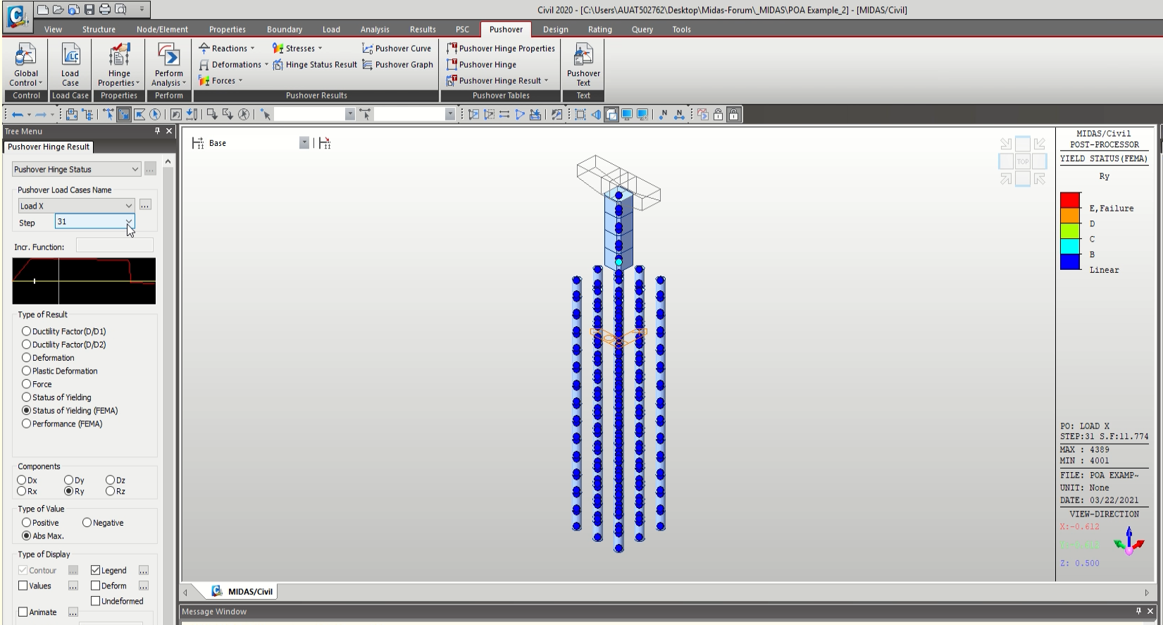 Figure 12. Pushover analysis results
References
1. S. Department of Transportation Federal Highway Administration LRFD Seismic Analysis and Design of Bridges Reference Manual
2. Association of State Highway Officials (AASHTO) Guide Specifications for LRFD Seismic Bridge Design 2nd
3. Association of State Highway Officials (AASHTO) LRFD Bridge Design Specifications
4. DPWH Design Guidelines, Criteria, and Standards (DGCS)
5. DPWH Bridge Seismic Design Specifications (BSDS)
6. Balakrishnan, V., Acosta, R. V. Jr., Matsumoto, N., Omori, T., Mizuno, K., & Obedi, O. D. 9th Australian Small Bridges Conference. Seismic Design of a Railway Viaduct in High Seismic Zone