Get Started midas Civil
 Featured blog of this week

This case study covers the following aspects:
1. Project Information
2. Advantages of Network Arch Bridges over Conventional Bowstring Arches
3. Modeling in midas Civil
4. Features for cable elements in midas Civil
5. Construction Stage Analysis
6. Moving Loads and Cables
7. Design and Checking Results
1. Project Information
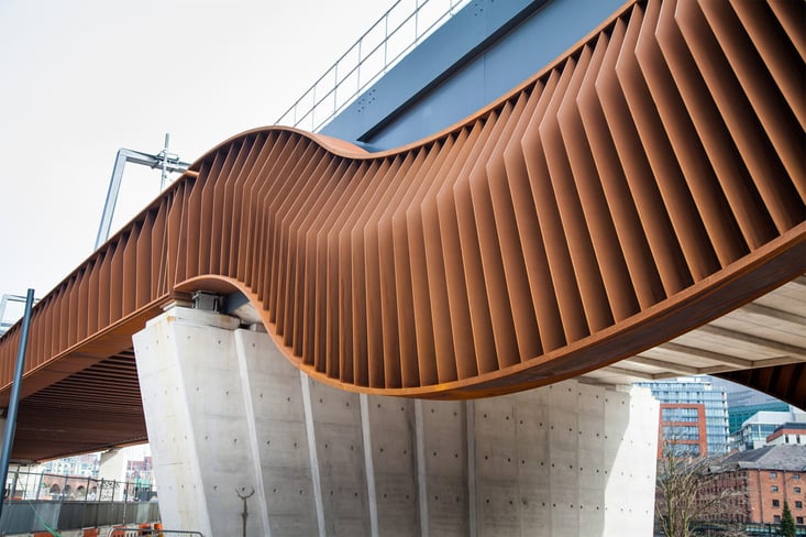
The River Irwell Network Arch Bridge is the centerpiece of the Ordsall Chord project, which connects Manchester Train stations of Victoria and Piccadilly, as part of the Great Northern Rail Project. The bridge presents a peculiar squashed tennis racket shape and is the longest spanning asymmetric network arch rail bridge in the world. It was the first Network Arch Bridge to ever be built in the United Kingdom.
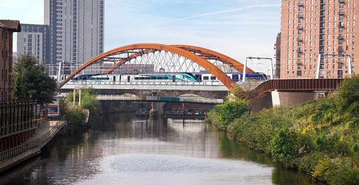
The total span of the structure is 89m, with an arch rise of 13.57m (rise to span ratio: 0.1525). In order to achieve a continuous linear development of the lines of the structure at the northern end side, the transition between the curved and straight girder is obtained through the use of a non-structural reversed curvature arch component.
/River%20Irwell%20Network%20Arch%20Bridge%20Modelling/new%20image%20River%20Irwell%20Network%20Arch%20Bridge%20Modelling/1.png?width=733&name=1.png)
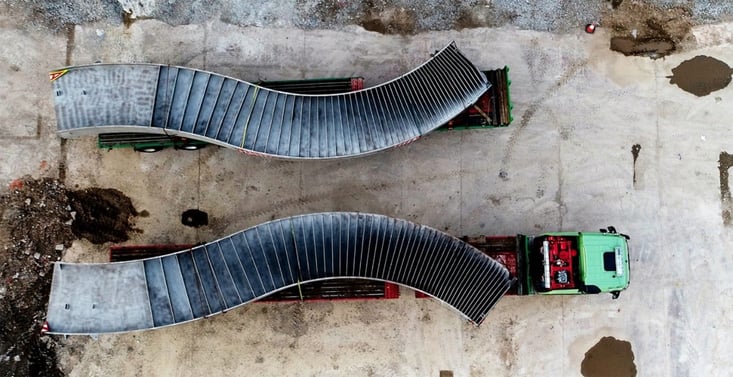
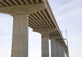
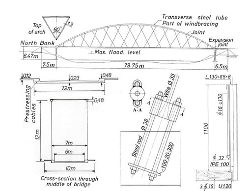
The bridge is 15.4m wide and carries two railway tracks in a curved alignment. Furthermore, it is designed for full LM71 loading (EN 1991-2:2003 + UK NA). The constraints regarding space at which the bridge will be erected were accounted for in the design. The erection method is based on the use of temporal asymmetric towers in order to speed up construction and make use of the same towers to dismantle the previous truss bridge at this location.
/River%20Irwell%20Network%20Arch%20Bridge%20Modelling/new%20image%20River%20Irwell%20Network%20Arch%20Bridge%20Modelling/Detailed%20Design%20Drawing%20(%C2%A9%20Network%20Rail).png?width=732&name=Detailed%20Design%20Drawing%20(%C2%A9%20Network%20Rail).png)
2. Advantages of Network Arch Bridges over Conventional Bowstring Arches
Typical bowstring arch bridges have vertical hangers or inclined hangers (Nielsen type). The tie closes the arch, taking in the spring (works in tension). This has the advantage of making arch bridges practical in sites with poor geotechnical conditions. Under UDL the arch is purely compressed and the tie-beam acts in tension.

Network arch bridges have inclined hangers crossing each other at least two times. The structural behavior is similar to a truss: arch structure in compression, tie beams in tension, and shear forces taken by the hangers. The father of this type of bridge is Prof. Emeritus Per Tveit, who conducted considerable research on the subject since 1950.
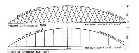
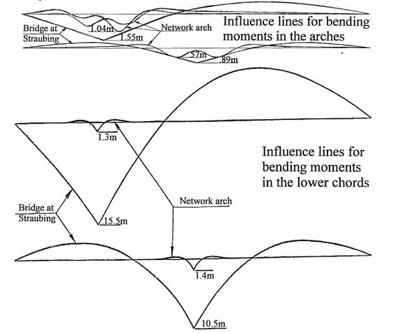
In the lecture by Dr.Per Tveit, he compared two arch bridges. One is an original bowstring arch and the other is a network arch bridge with the same span length as the bowstring arch. Dr. Per Tveit calculated the influence line for the bending moment for both arch bridges. The network arch showed lower influence lines for bending moments than that of a tied beam arch. The point is that the network arch can be a very effective structure which leads to materials and weight-saving for long-span bridges.
The River Irwell Network Arch Bridge analysis was studied using midas Civil as shown in the figure below. Two element models were created. Load conditions, boundary conditions, and all other conditions are the same except for the cable shape.
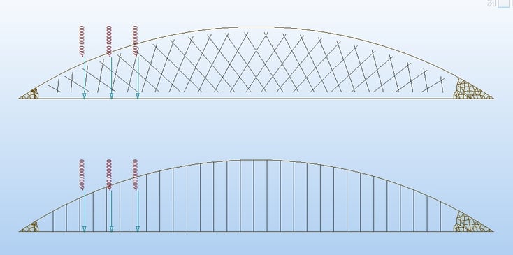
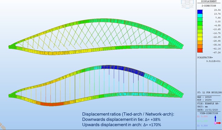
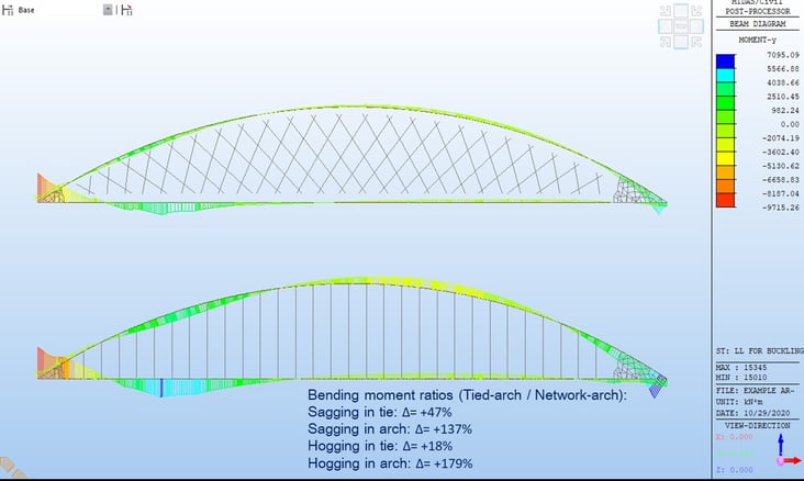
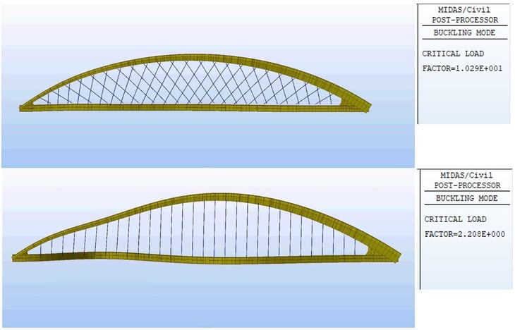
Analysis results have shown that the network arch bridge is a more effective structure than the bowstring arch bridge with regards to displacement, bending moments, and buckling.
Recap of advantages of Network Arch Bridges over Bowstring Arches:
1. Network Arch bridges induce lower bending effects in members
2. Network Arch bridges show higher stiffness against deflections in members
3. Network Arch bridges show higher stiffness against lateral buckling
4. Network Arch bridges allow for higher redundancy in the cable-out case
5. Network Arch bridges allow for the design of slender structures
6. Network Arch bridges allow for savings in material and more economical designs
Network Arch bridges are suitable to efficiently cross longer spans, achieve higher redundancy levels, better material utilization, and overall more economical and environmentally less impactful designs.
3. Modeling in midas Civil
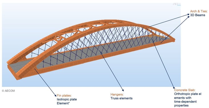
Bridge members have been modeled by using various elements in midas Civil. Arch and tie members consist of 3D beam elements. In order to consider a composite girder, the concrete slab of the girder is modeled using orthotropic plate elements with time-dependent properties. Truss elements are used for hangers. The connection of arch and ties has been modeled using isotropic plate elements. The use of plate elements for the fin plates allows for a better representation of the local stiffness of the knuckle joint connection in the global analysis model. This, in return, avoids unreal spikes in stresses and/or BM concentrations. It also allows for a more realistic interpretation of the local stiffness, which is a very important factor in capturing the behavior of the structure in terms of effects/displacements.
The following modeling process was used in midas Civil.
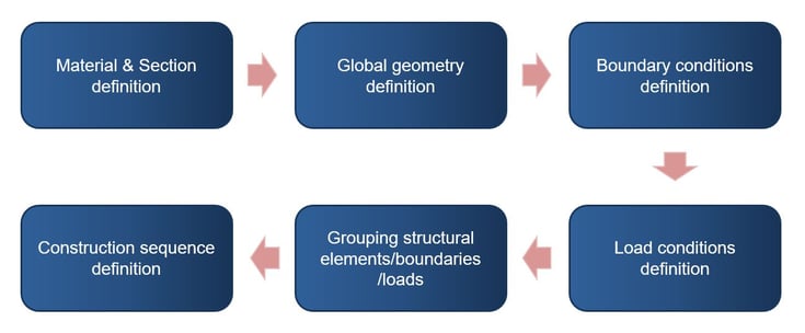 Figure 15: Modeling process in midas Civil
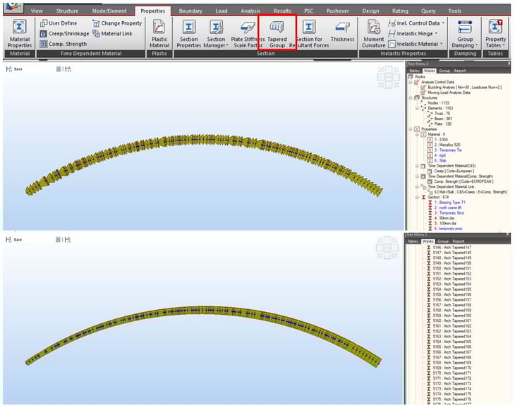
Some sections in the bridge are not typical sections. Those sections have been defined using Sectional Property Calculator (SPC). It allows the user to define various sections based on a drawing. The arch member consists of a lot of beam elements. However, the arch member had a tapered shape, so inputting the various sections into each element was a challenge. In this case, the Tapered Group function was used. It allows the user to define start/end sections and create all sections in between using linear or polynomial variations. Each section can be defined as a new section property (and imported in other models).
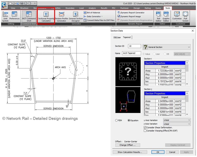 Figure 16: Sectional Property Calculator & Tapered Section Property
In this model, the concrete slab has been modeled using orthotropic plate elements. Before modeling, three types of modeling method were considered:
-
Equivalent orthotropic material for RC plate
-
Using stiffness modifiers
-
Beams grillage
The equivalent orthotropic material for the RC plate method is assigning equivalent orthotropic materials to plate elements. By using codified material properties in the equations on the right-hand side and by inverting the equations on the left-hand side using the results obtained we determine all necessary parameters for the equivalent reinforced concrete plate: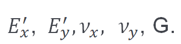
After that, those results can be inputted into material properties directly.
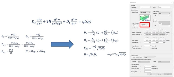
The second method consists of using a stiffness modifier function in SW. By using this function, we can control in-plane stiffness and out-of-plane stiffness by ratio. For this case, the Plate Stiffness Scale Factor function was used. This function has a grouping option so the user can apply it to the desired construction stage.
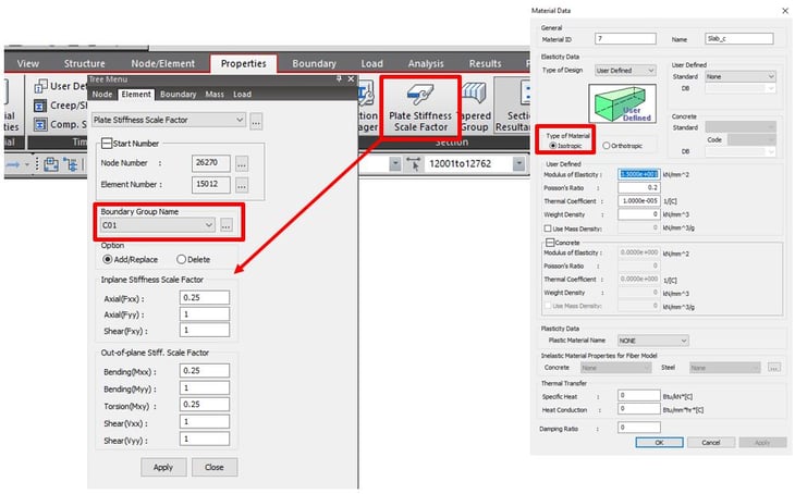
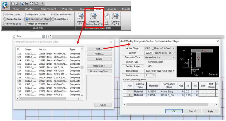
The last method is to model the concrete slab using beam elements as a grillage model. In this case, the deck is modeled by using transverse composite section beams and longitudinal concrete-only beams using cracked section properties. Composite Section for C.S. function in midas Civil was used to consider composite sections during construction stage analysis.
4.Features for cable elements in midas Civil
Before discussing cable elements, let’s first look at a comparison between truss and cable elements.
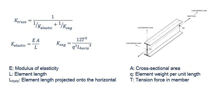
The truss element:
- Axial forces only element.
- Considers decreased axial stiffness of element due to sag effects.
- Does not calculate actual sag.
- Tension/Compression only elements (If selected).
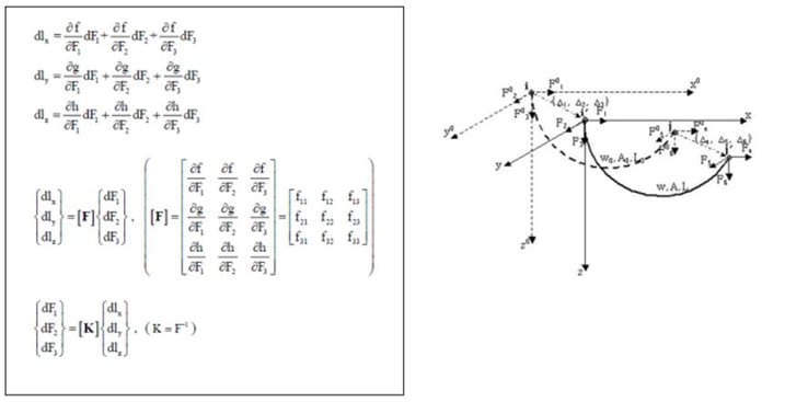
The cable element:
- Tension only elements
- Non-linear in behavior due to sag effects (Non-linearity in geometry) – i.e. large displacement analysis
- Directly reflects changes in stiffness due to changes in tension level in elements – i.e. explicitly calculates sag.
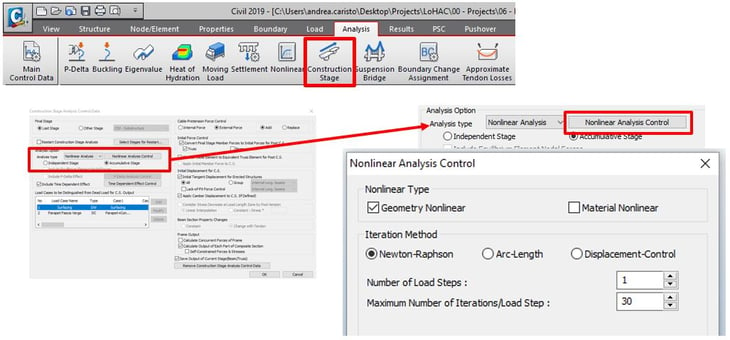
Therefore, to use a cable element, the user needs to perform a full non-linear analysis, making use of the tangent stiffness. However, the non-linear analysis is not always necessary. Usually, non-linear analysis is used for long-span bridges over 500m and when cable forces in the stage are low. It causes the sagging effects to be the dominant force. Midas Civil has been providing a peculiar feature to use cable elements easily.
When the user considers cable elements in a construction stage analysis, the following options should be considered. In order to conduct a non-linear analysis, the user needs to switch on the non-linear analysis controls in the Construction Sequence panel. As the system is non-linear, superimposition is lost and Accumulative Stage effects are to be considered. The software will update the tangent stiffness of the cable at each stage and take into account large displacements by explicitly calculating the sag of the elements.
.
The other option is the re-stressing of cables in force-control. Typically, the software requires the modeler to obtain the final stressing either by changing the element length (imposed elongation) or by deactivating and reactivating a new element by assigning first stressing into it. MIDAS Civil has introduced the concept of treating applied pretensions as “External” type forces. Through this option, the user can replace or add a new force into existing cable elements without deactivating or reactivating elements.
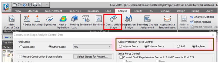 Figure 25: Cable-Pretension Force Control option in Construction Stage Analysis Control
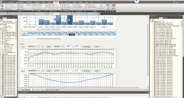
/River%20Irwell%20Network%20Arch%20Bridge%20Modelling/new%20image%20River%20Irwell%20Network%20Arch%20Bridge%20Modelling/11.png?width=600&name=11.png) Figure 26: Cable forces at the same element in different stages
Figure 26: Cable forces at the same element in different stages
Here are two more functions regarding cable elements. The first one is the Cable Force Tuning function. It allows the users to interactively change forces in cables and see results change in real-time on-screen. This helps reduce the number of iterations required to find the optimum tensioning of cables based on displacement/stress/member forces or hanger loads.
The other is the Unknown Load Factor function. It allows solving goal-seek problems using multiple constraints. This helps reduce the number of iterations required to find the optimum tensioning of cables based on displacement/stress/member forces or hanger loads constraints.
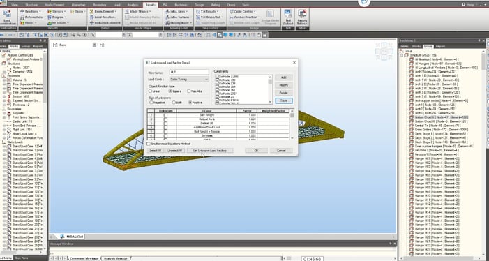 Figure 28: Unknown Load Factor function
From this function, the influence matrix for hangers was obtained to quickly assess the effect of stressing any given hanger on all other hangers.
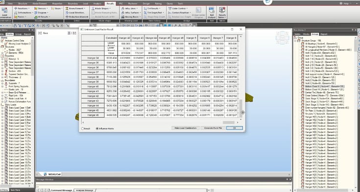
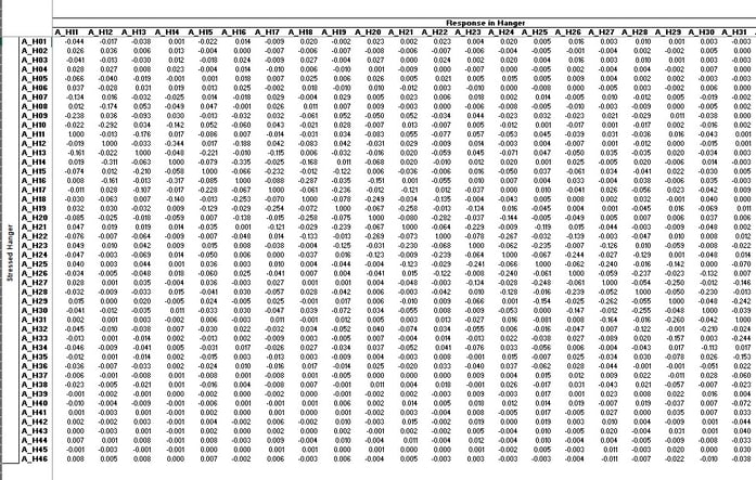 Figure 29: The influence matrix for hangers in ULF function and excel sheet
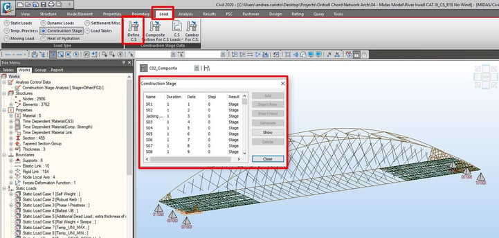
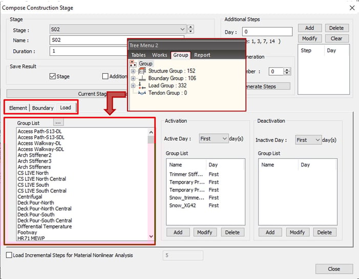
5. Construction Stage Analysis
After modeling for the whole bridge, several groups for elements, boundaries, and loads were created in midas Civil. midas Civil supports the construction stage analysis. The concept of the construction stage analysis is that several groups for elements, boundaries, and loads are activated or deactivated along the stage as the real-construction plan. Furthermore, additional steps can be defined in a construction stage so a lot of construction phases can be easily managed. In order to see the detailed process of construction stage analysis in this project, please refer to the video below (38:00~48:30).
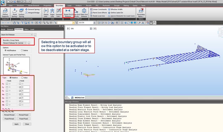
Additionally, certain boundary conditions such as Beam End Release can be applied to the desired construction stage by assigning the condition into a boundary group.
6. Moving Loads and Cables
The moving load analysis is also conducted in midas Civil. The process of moving load analysis is:
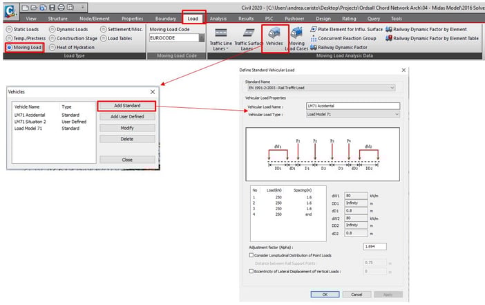
1. Traffic lane definition
2. Vehicle definition
3. Load case definition
4. Run
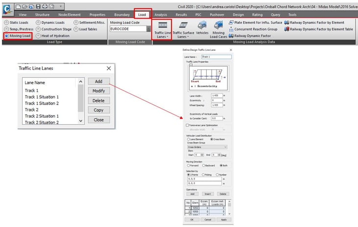
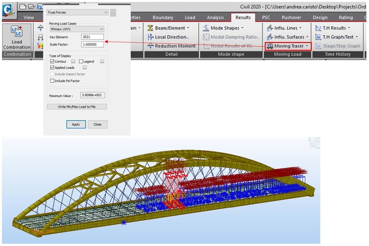
The Moving Load Tracer function can be found in the Results menu of midas Civil. It allows users to see a distribution of moving load to assess the specified effect.
When the user runs a moving load analysis with a model using cable elements, a warning message will show in midas Civil saying “Cable/Tension-only truss elements are converted to Truss elements for moving load analysis”. This means that midas Civil converts nonlinear elements into linear elements. When the moving load analysis is conducted with tension-only elements and truss elements for cables, the user can see the results below. Particularly, the model with the truss elements for cables shows truss elements under compression under a moving load case for the minimum case. When a moving load analysis is conducted in midas Civil, midas Civil shows enveloped results for the maximum and minimum case. In order to check corresponding forces, the user needs to check results using the Moving Load Tracer. Figure 34 shows the compressed truss elements, and compression here means relieving effects on cables.
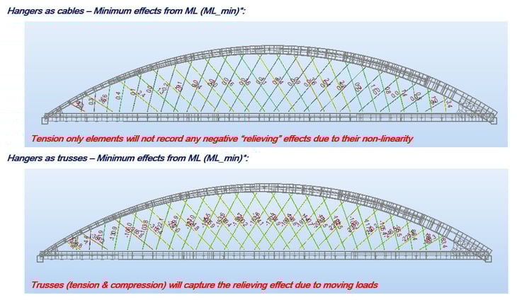
Therefore, placing moving loads as static loads with tension-only elements in a “linearized” (superimposition) analysis will not capture the relieving effect in the cable. When MIDAS converts cables to linearized elements, which is a correct approach, it allows the user to use influence lines for moving load analysis.
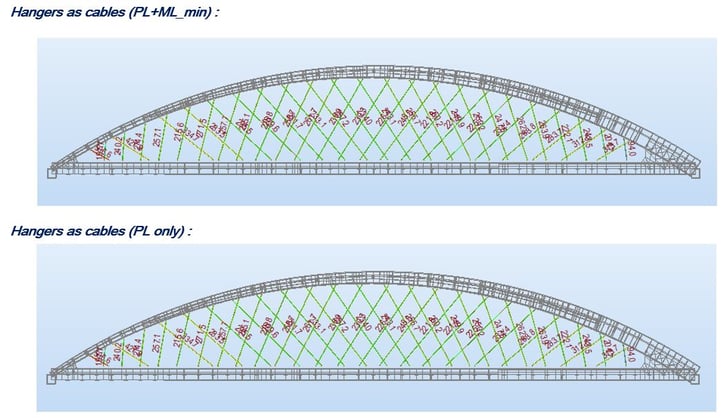
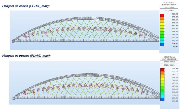
Figure 36 shows the results for the combination of permanent loads and moving loads (the maximum case). There is a considerable change in final forces between the two systems. If cable/tension only truss elements are used for cables for moving load analysis, midas Civil will ignore the relieving effect and imposition for all cables. The hangers as trusses are the real behavior result, and this is due to the fact that the stiffness of the structure is correctly captured. In order to correctly use cables, the user will need to place a moving load in the correct Influence line positions and run a Non-linear analysis with the “Load cases created from Load Combinations” function.
7. Design and Checking Results
Structural element checks are carried out in accordance with BS EN 1992/1993/1994. Most plated elements are class 3 or 4, so local buckling is important in the design. Global stability was checked through non-linear buckling analyses carried out in MIDAS Civil, based on the buckling shapes obtained from linear buckling and by identifying the load factor associated with failure under the specific load condition and buckling shape, including imperfections as specified in BS EN 1993-2. Regarding cable-out load cases, accidental LL position extracted from moving load tracer and hangers removed. Equivalent static load technique used for this analysis (dynamic amplification factor applied to original hanger forces).
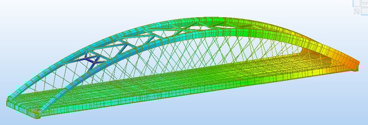
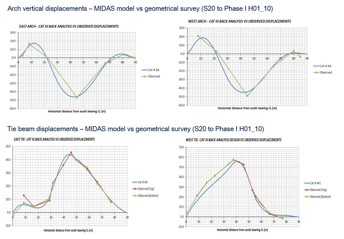
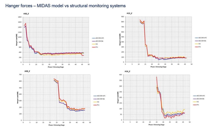
Figure 37: Analysis model in results view
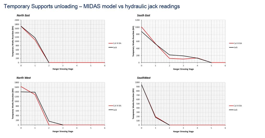
From midas model, the results regarding reaction forces, internal forces, and displacements at members of the bridge have been compared with real systems such as hydraulic jacks, geometrical surveys, and structural monitoring systems. The comparison results have shown that reasonable results obtained from the midas model.
Watch the full webinar video
Q&A
Question 1
Can we talk about the arch plan bracing design concept?
Answer 1
The wind bracing used for the River Irwell bridge is made up of K-bracing. In my opinion, this is the most typical bracing used for railway structures of this type and is basically the one shown in the MSc Thesis by Brunn & Schanack and in multiple papers by Professor Tveit.
The sections used on the River Irwell are rectangular hollow sections 380x400 with 12/15mm thicknesses.
The function of the bracing is obviously to carry wind loads limit the buckling length of the single arches and connect the two in the out-of-plane response. This enhances the overall lateral buckling response of the structure. These members take self-weight, wind forces, and restraining forces from the arches due to out-of-plane deformations.
Their structural design was checked against the forces induced by the prominent buckling mode of the arches, scaling the imperfection at the midpoint as per Eurocode 1993 and the other actions.
Question 2
Can you describe the various cases of cable loss? Was there a case of direct impact on the stays by the train? Did you just use PTI requirements for cable-stay bridges?
Answer 2
The scope of work included the check of any 4 adjacent cables snapping simultaneously. If I understand the question correctly, you are asking if the train load during derailment was applied in the model as an out-of-plane load and the models ran with non-linear analysis with dynamic effects of cables snapping (i.e. time history with material non-linearities). If this is the question, no - The calculation was done by considering the PTI requirements (i.e. the incremental DAF to the static force). This is in line with what is recommended by the MIDAS support when dealing with cable-out cases (see the MIDAS Technical query forum).
Question 3
Did you assume any tension force is taken at the level of the deck? Did you bound the solution by making the membrane stiffness of the deck zero - in order to maximize tension in the tie beam?
Answer 3
The membrane stiffness in the deck was calculated for the fully cracked section longitudinally – i.e. the forces were maximized in the ties. The stiffness of the plate was not set to zero, but the longitudinal reinforcement was considered for the stiffness (this is lower than the full plate stiffness, but is not zero for the membrane effects).
Question 4
Thanks for the great presentation. Is the aerodynamic effect taken into consideration in the fatigue check for the hanger?
Answer 4
Vortex shedding for the hangers was calculated and the cross-displacement was determined (see BS EN 1991-1-:2005). This did not result in an impact on the fatigue life of the hangers due to wind alone.
Fatigue testing on the hangers was particularly demanding from the contract: each hanger diameter present on the bridge was tested to 2 million cycles to determine the behavior in fatigue, as the system was previously granted European Technical Approval under static loads only.
Question 5
I understand bearingless construction is preferred in the UK. Why is this not used on this bridge?
Answer 5
True, but I have not seen it used for this type of structure. The only integral arch bridges I know of are mainly pedestrian and have been designed by Strasky (see here) – as far as I am aware these were not Network Arches.
Usually, integral forms here in the UK are used for frame portals (on full height or piled abutment). The reference code for these types is PD6694-1 in the UK.
I don’t know of one network arch bridge that acts integrally with the substructure. I must admit I haven’t personally considered the case of making the structure integral either. I’d be curious to see if it would have any advantages. If you do have material, please share it with me. Thank you!
Question 6
Presumably is there a limitation on span length?
Answer 6
Typical integral abutment bridges would be limited by the span. BA 42 suggests all highway bridges below 60m should be made integral where possible (this is due to lower expected maintenance costs). The span limit usually is dictated by what is practicable to design when soil ratcheting is considered. But this refers to “frame” type bridges, with abutments loaded directly by the backfill.
Some research has gone into ways of isolating the bridge structure from the backfill in later years. This would allow us to reduce the associated strain ratcheting effects and help achieve longer spans (see here for one of such research papers).