 Get Started midas Civil
 Featured blog of this week

Contents of the article:
-
Introduction to Traffic Load Consideration
-
Significance of Influence Line Analysis
-
Moving Load Analysis for Various Types of Bridges
-
Case-Studies
-
Questions & Answers
1. Introduction to Traffic Load Consideration
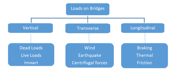
Loads on bridges can be permanent and transient. Live Loads on bridges are typically dynamic in nature. These could be due to traffic, rolling stocks, locomotive, etc. The vertical and horizontal components could be analyzed as static analysis with appropriate dynamic amplification factors to account for the dynamic effects based on the type of bridges adhering to code provisions. Live loads applied on the structures, unlike permanent loads, do not have a fixed position on the bridge structures and can be placed at critical positions as the traffic moves over a span.
Hence, we would require the Moving Load Analysis, typically a Static Load Analysis finding the worst load effects out of various possible positions along the bridge based on the Influence Line analysis or influence surface analysis.
2. Significance of Influence Line Analysis
-
Definition: The influence line for a response function is given by the deflected shape of the released structure due to a unit displacement (or rotation) at the location and the response function's direction.
-
Response Function = support reaction, axial force, shear force, or Influence Line Definitions bending moment.
-
Influence Line/Influence surface = graph of a response function of a structure as a function of the position of a downward unit load moving across the structure.
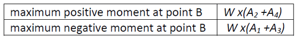
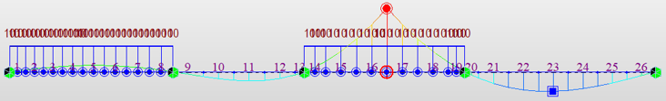
For example, in fig.1, for the two-span continuous bridge, to obtain the maximum sagging at point “A” span, which is at the mid-span, would be loaded to create a positive influence.
Similarly, if the second span is loaded, this would have a reliving effect for the maximum sagging moment at A.
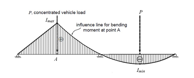
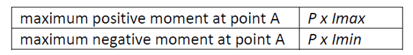 Fig 2.1 Calculation of maximum/minimum moments due to a concentrated vehicle load (P)
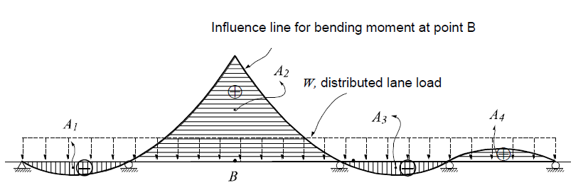
The effect of a moving load on the magnitude of certain functions of a structure, such as support reactions, deflection, and shear force and moment, at a section of the structure, varies with the moving load position.
In the program, a set of concentrated loads would be applied considering all the loading conditions along the moving direction of the traffic to find the maximum and minimum values.
Hence, Influence line analysis is important in determining the critical position of moving loads.
3. Moving Load analysis for various types of bridges
To find the most critical design parameters (member forces, displacements, and support reactions) in the analysis of a bridge structure, all the conditions of vehicle loads must be considered.
Especially, when a number of design vehicle load groups and traffic lanes are involved, all the conditions that may affect the design parameters must be analyzed:
a) if the vehicular load groups are loaded simultaneously;
b) if only the critical-case design vehicle load group is to be applied among the load groups;
c) if a specific lane is selected for loading the design vehicle load groups; and
d) what load reduction factor is to be applied if a number of traffic lanes are loaded.
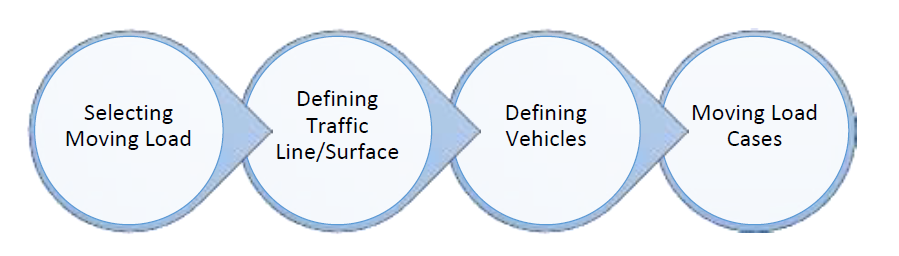
Defining Moving Load definition as per the various standards is 4 step process in midas Civil.
Once the moving load analysis is completed the results will be generated using the influence line results.
I. Selecting the Moving Load Code: Moving Load can be selected through different standards.
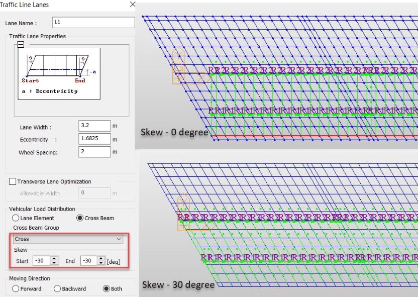
II. Defining Traffic Line/Surface Lanes: Specify the centerline of the vehicle considering the
eccentric positions of the vehicles.
The distribution of the vehicular load is by two methods:
Lane element: Traffic Load would be applied directly to the reference elements (Vertical Concentrated load and moment). This method is applied in the case of line beam models.
Cross Beams: Traffic load will be applied at the actual location and will get distributed to longitudinal girders through Cross-Beams. Generally, this method is recommended for the Grillage Models.
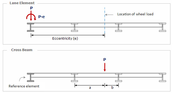 Fig.3.2 Load distribution through Lane element and Cross Beams (source: online manual)
Another way of defining traffic lanes would be through the Moving Load Optimization Option.
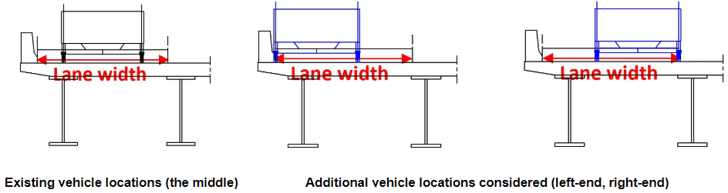
Moving Load Optimization will automatically consider the placements of the lanes in the transverse and longitudinal direction along the entire carriageway considering the positions on the Left, Right, and Center.
Defining the individual traffic line lanes can be avoided through the moving load optimization option. Hence, the lanes are loaded in such a manner that it gives the most critical moving load envelops.
III. Defining the Vehicular load:
The standard load models according to different standards can be defined directly added.
However, in case any User-defined loads need to be added then that case such loads can be defined through three options based on the moving traffic load code as below
- Truck/Lane
- Train Load
- Permit Truck (heavy loading vehicle)
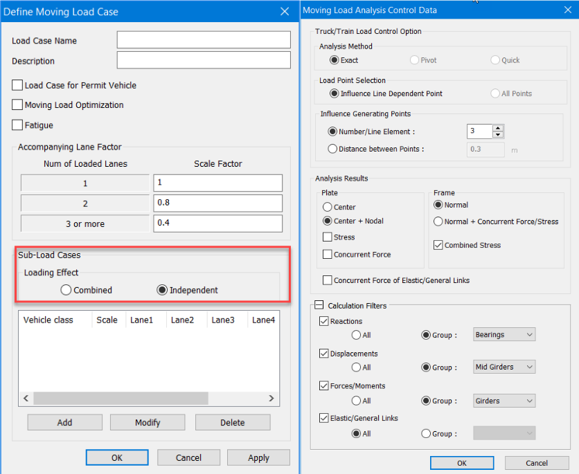
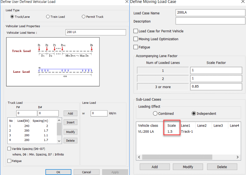
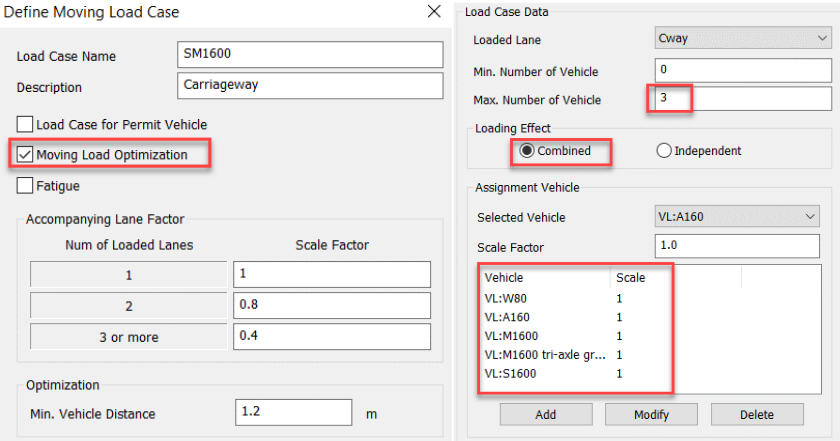
IV. Defining Moving Load Cases:
-
Moving Load cases option allows combining the different classes of vehicles in one moving load case considering the minimum and maximum lanes to be loaded.
-
Hence, the repetitive task of creating the individual load cases and then making a combination of all the vehicles can be avoided.
- Loading effects: Combined - Combination of vehicles.
Independent
- Vehicles applied independently
-
In the case of complex models consisting of numerous elements, running moving load analysis can be time-consuming. However, with the moving load analysis control selecting specific girder group elements can be chosen to reduce the analysis time.
-
Hence, with the Moving load analysis control option variety of parameters such as selection filters for specific result group output can be controlled and hence the run-time of the model.
-
It is always recommended to cross verify the program results with simple manual calculations
4. Case-Studies
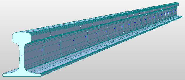
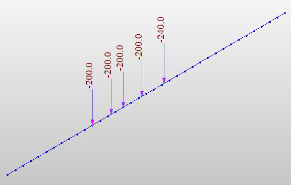
i. Line Beam Models - Case Study 1 (Rail Seat Loads)
Purpose: 2D Line beam model was created to obtain the maximum reactions at the sleeper or the rail pad under the rail.
Configuration
- Span: Multi-span continuous
- Alignment: Straight
- Section: UIC 60 kg/m rail
- Moving load: 200LA (rail)
- Carriageway: Single Track
- Application: Traffic Line Lane
User-defined rail load can be directly specified using the User-defined vehicular load option and dynamic amplification factor for the same can be accounted for by just defining the scale factor.
However, scale factors can be used as Impact factor/CDA, Load combination factor, etc.
Dynamic amplification can however be applied at the time of creating the load combination in an excel sheet. However, applying it when creating the moving load cases would be easy to get the final results.
/Contents/Case%20Study/new%20image%20Traffic%20Load%20Consideration%20to%20Different%20Types%20of%20Bridges/Multi-span%20continuous%202.jpg?width=672&name=Multi-span%20continuous%202.jpg)
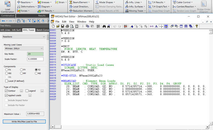
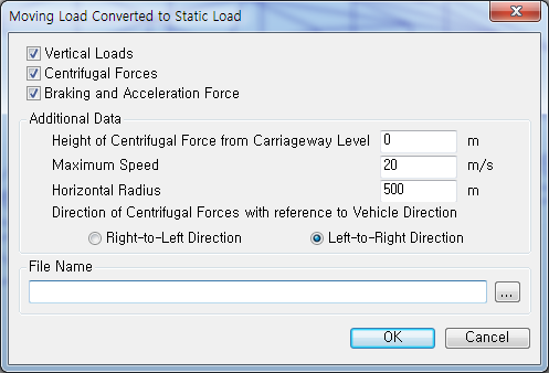
The results of the moving load cases can be converted to static load cases.
Converting moving load into a static load.
Write Min/Max Load to File
From the envelope of all load positions, the load position most critical for a particular node can be extracted into a static load case.
i. Line Beam Models - Case Study 2 (Pedestrian Bridge)
Purpose: To directly incorporate the pedestrian load using the code reference and also to model the traffic live load on curvature.
The moving load on the curvature can be directly assigned just by specifying the elements numbers which are in a sequence that generally do not lie on the straight line.
Pedestrian load intensity is dependent on the loaded area which is predefined in midas Civil.
If for the continuous structures, different load intensities need not be assigned in case only a few or all the spans are loaded since midas Civil automatically calculates these intensities for the different loading patterns.
- Configuration
Span: 4 spans continuous
Alignment: Curved
Section: Steel box girder
Moving load: Pedestrian load
Carriageway: 2 x 2.5m wide shared path
Application: Curved lane, pedestrian load
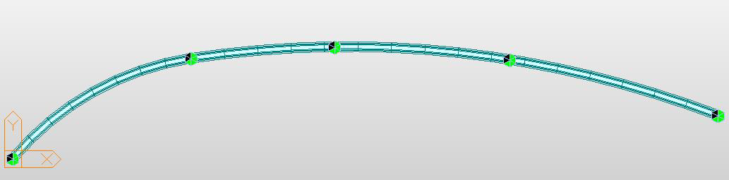
The location of the concentrated loads for the maximum sagging moments, shear, or the reactions can be obtained along with the influence line diagram
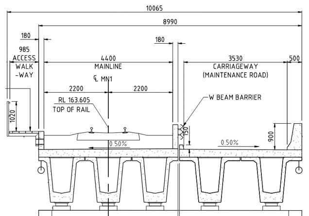
i. Line Beam Models - Case Study 3 (Road Bridge)
Purpose: To carry out the structural assessment of the bridge for the T44/L44 vehicles.
In this case, the moving load optimization was used in the 2D line beam model in order to avoid the manual definition of the individual lanes.
However, this method can only be used when the individual lanes to be defined have the same properties.
Configuration
- Span: 2 spans continuous
- Alignment: Straight
- Section: Box girder
- Moving load: T44/L44
- Traffic lanes: 3 lanes
- Application: Moving load optimization
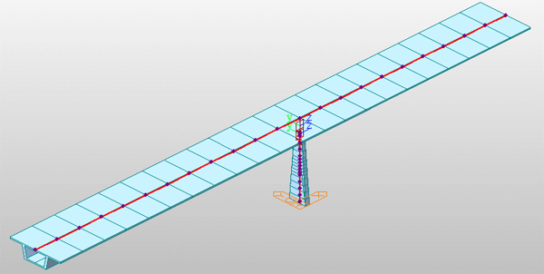

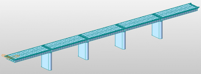
ii. Grillage Model - Case Study 1 (Straight Bridge)
Purpose: To find the critical response due to moving loads in Grillage Models.
When the combining vehicles have similar vehicular configuration, traffic lane width, and wheel spacing, then the Moving load optimization can be used.
If different vehicles are required to be combined, different traffic lanes need to be created.
Configuration
- Span: 1 span simply supported
- Alignment: Straight
- Section: Super-T + Deck
- Moving load: SM1600, HLP320 (Road)
- Carriageway: 6m, 3 lanes
- Application: Traffic lane for grillage, Combining vehicles
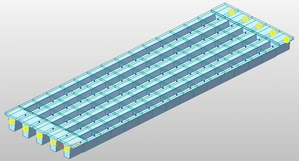
ii. Grillage Model - Case Study 2 (Skew grillage)
Purpose: To find the critical response due to moving loads in Grillage Models.
Incorrect skew will leave some portion of the deck outside the traffic lane extents and hence traffic loads will not be run in this portion of the deck.
When the multiple lanes having the same vehicular configuration needs to be combined in the direction of the left skew for the right skew can be done by directly selecting the load effect as “Independent”
Once the analysis is completed, the concurrent forces due to moving loads can be obtained.
Configuration
Span: 6 spans simply supported
Alignment: Skewed (30 degree)
Section: Plank + deck
Moving load: SM1600, HLP
Carriageway: 9m, 2 lanes
Application: Skew deck
ii. Grillage Model - Case Study 3 (Rail+ Road Bridge)
Purpose: Due to different vehicular loads, moving load optimization cannot be used. Hence, in order that transverse lane optimization is required to be defined.
Since the available carriageway width is more than that of the design width, transverse lane optimization can be used.
However, when defining the Traffic lane for the railway loading transverse lane definition is not to be selected since the track position is fixed.
Configuration
- Span: 5 spans simply supported
- Alignment: Straight
- Section: Multi-girder bridge
- Moving load: 350LA + SM1600
- Carriageway: 1 Track + 1 Lane
- Application: Rail + Road load, Transverse lane optimization
iii. Planer Models- Case Study 1 (Box Culvert)
Purpose: To perform the load rating on the bridge structure
Configuration
- Span: Single span
- Alignment: Straight
- Section: Solid slab roof and walls.
- Moving load: T44, M1600, HLP400
- Carriageway: 12m wide (multi-lane)
- Application: Traffic surface lanes, optimization, permit vehicles.
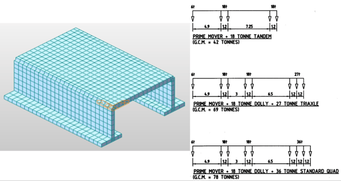
The permit truck can be defined using the User-defined vehicular loads by inputting the multiple axles and spacing’s.
Eccentricity: Input the distance of the Permit Vehicle to the Ref. Lane. By looking towards the direction the vehicle travels, the right side is considered positive and the left side is considered negative.
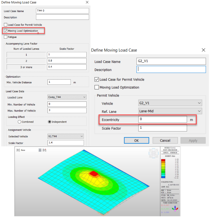
fig. Influence Surface-Mxx
SUMMARY
-
Moving load analysis based on Influence line/surface
-
Moving load analysis features
-
International codes, predefined and user-defined vehicles
-
Traffic line lanes, transverse floating of vehicles within a lane
-
Moving load optimization – auto lane definition
-
Moving load case – several scenarios can be combined in one load case.
-
Moving load analysis control – filter the results, reduce run time
-
Variety of result outputs
-
Diagrams/contours for force, displacement, stresses, reaction, etc.
-
Result tables, concurrent forces/reaction
-
Moving load tracer - visualize vehicle positions, write load to file.
5. Questions and Answers
Q1. How do you determine eccentricity in traffic lanes?
A) Eccentricity is the distance from the centerline of the traffic lane to the reference elements used to define traffic lanes.
Q2. How can you define braking loads?
A) When BS or Euro code is selected, braking loads can be obtained when creating a static load case from the moving load tracer tab. See below: Although this functionality is currently not available for all codes, you may have to load it manually.
Q3. In using Traffic Load Optimization for transverse vehicle position within the lane, does MIDAS individually float the vehicle positions in adjacent lanes to generate the most onerous results? Eg. Lane 1: vehicle left-hand side of the lane, Lane 2: vehicle right-hand side of the lane, etc.). Note on Slide 55, all loads were either LHS or RHS. For a central girder, will it consider some lanes LHS, others RHS?
A) Yes, Midas will float the vehicles individually in each lane to produce the worst effects.
Q4. Is it possible to input numerous vehicles on the carriageway simultaneously based on actual scenarios?
A) Yes, different vehicle types can be combined together in a carriageway. Although in a multi-lane loaded scenario, within an individual traffic lane only one vehicle type will be loaded.
Q5. Is there any way to tabulate results for several beams after I use Moving Load Tracer?
A) If you wish to create a static load case for several beams, this can be done by Batch conversion (available in the moving load tracer tab). After obtaining static load cases, you need to analyze the model again. The results can now be obtained for each static load case in a tabular or graphical form.
Q6. Is there a way to define vehicular moving load to a curve & ramping up at the same time?
A) Yes, this can be defined in the same way as you would do for a flat bridge. Although additional horizontal load effects won’t be considered by the software automatically.
Q7. How about the moving load on the curved bridge with superelevation?
A) Moving load can be run on a curved bridge with superelevation. Although an only vertical components of wheel loads will be considered. For rail traffic loads, an eccentricity can be input to account for unequal wheel load distribution. See below:
/Contents/Case%20Study/new%20image%20Traffic%20Load%20Consideration%20to%20Different%20Types%20of%20Bridges/How%20about%20the%20moving%20load%20on%20the%20curved%20bridge%20with%20superelevation%3F.jpg?width=734&name=How%20about%20the%20moving%20load%20on%20the%20curved%20bridge%20with%20superelevation%3F.jpg)
Watch the Full Webinar Video Here:


/Traffic%20Load%20Consideration%20to%20Different%20Types%20of%20Bridges/Vishal.jpg)


/Traffic%20Load%20Consideration%20to%20Different%20Types%20of%20Bridges/2_Traffic%20Load%20Consideration%20to%20Different%20Types%20of%20Bridges.jpg)

/345%20240/Moving%20load.png)
/345%20240/5.png)