Get Started midas Civil
 Featured blog of this week

Interpreting Construction Stage Analysis
Table of Contents
1. Introduction
2. Accumulative Construction Stage Analysis
3. Independent Construction Stage Analysis
1. Introduction
Construction Stage Analysis is when you check the behavior of your structure at certain construction stages. Please take note that Construction Stage Analysis does not necessarily mean that you can only perform this on the interim/intermediate configuration of your structure to accumulate result up to the final and completed structure.
Construction Stage Analysis can also be done to check your final structure for certain failure that may occur in the future, or you can also use this to check your structure for its long-term effects, such as creep (additional deformation the concrete will experience through time without additional loads), shrinkage (reduction of volume in concrete material due to loss of moisture), and relaxation of prestressing tendons.
You may read this article to know more about Construction Stage Analysis: https://www.midasbridge.com/en/solutions/construction-stage-analysis
There are two types of Construction Stage Analysis:
1. Accumulative Construction Stage Analysis
2. Independent Construction Stage Analysis
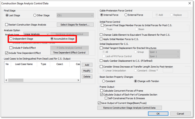
2. Accumulative Construction Stage Analysis
Accumulative Construction Stage Analysis is when the resulting forces and moments of previous construction stages are taken into consideration on the succeeding stages. This is done by summing up the result of the current construction stage considering only the loads that are being activated and the result of the previous construction stage.
To easily visualize the result of Accumulative Construction Stage Analysis, let’s take the simple beam below as an example. This is a 3@10m span simple beam loaded with a uniform load of 1kN/m all throughout. Self-weight of the beam will not be considered.
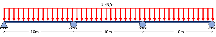
Suppose this beam is to be constructed by launching one span at a time together with the corresponding uniform load per span.
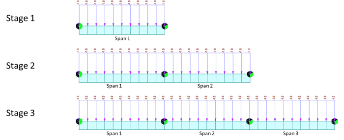 Figure 2.2 Construction Stage Example
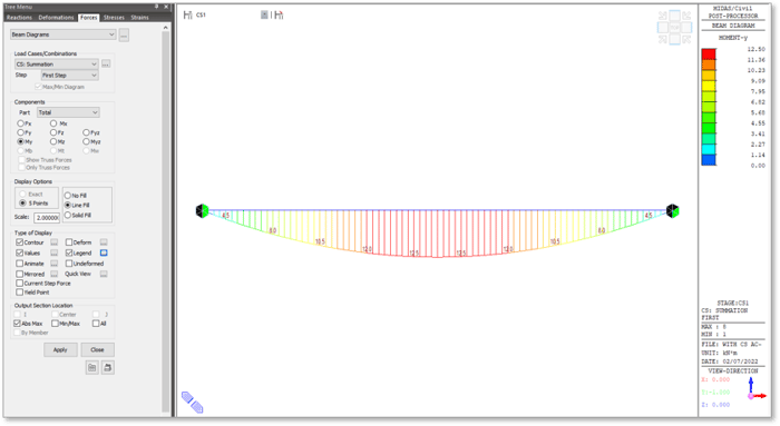
Let’s say we want to check the accumulative results for the moment diagrams of these three stages. First, a moment diagram for Stage 1 will be taken:
For Stage 2, the moment diagram will be taken considering the two spans and the loads that will activate on this stage only (Current Step Force), and to be summed up with the moments at Stage 1.
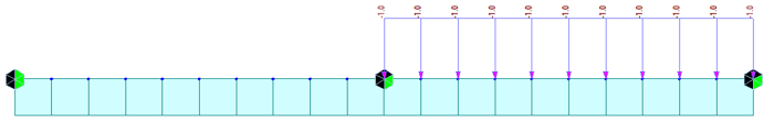 Figure 2.4 Current Step for Step 2
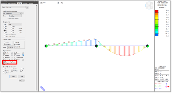 Figure 2.5 Current Step Force Moment Diagram at Stage 2
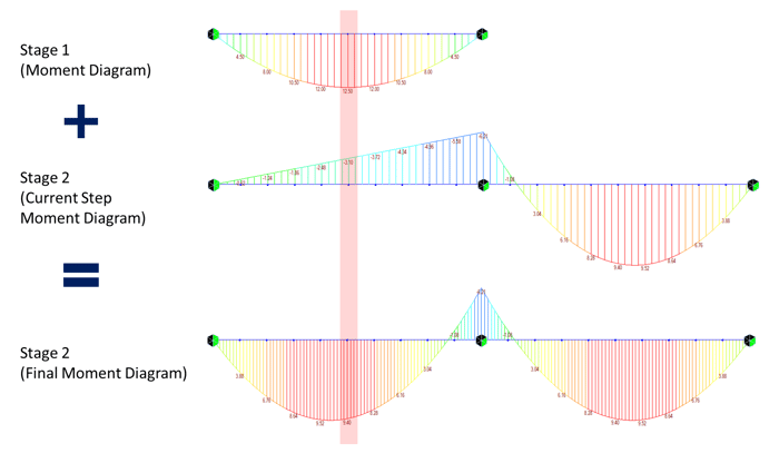 Figure 2.6 Derivation of Stage 2 Final Moment Diagram
On the shaded region in Figure 2.6, you can see that the moment 9.4 kN-m at Stage 2 (Final Moment Diagram) is taken by summing up the moments 12.5 kN-m at Stage 1 (Moment Diagram) and -3.1 kN-m at Stage 2 (Current Step Force Moment Diagram).
The same principle is applied to get the final moment for Stage 3.
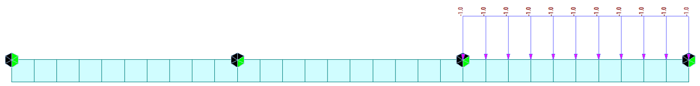 Figure 2.7 Current Step for Stage 3
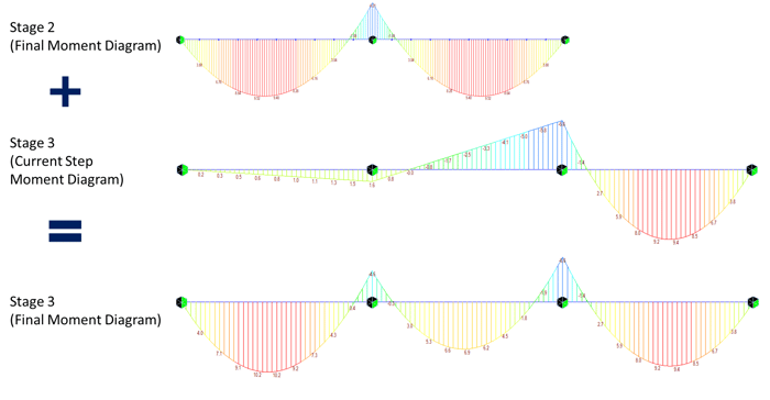 Figure 2.8 Derivation of Stage 3 Final Moment Diagram
You may download this sample model if you want to try generating these moment diagrams on your own.
3. Independent Construction Stage Analysis
Independent Construction Stage Analysis is when the resulting forces and moments of previous construction stages are not considered. On this type of constructions stage, you will analyze the current configuration of the structure at a certain stage as it is.
This type of construction stage is usually used to analyze the completed structure at certain failures. One example is the Cable Snap Analysis for Cable-Stayed Bridges where one cable is deactivated in a stage and structure is checked for stability and design capacity if that particular cable breaks. In the next stage, that cable is activated, and another cable is deactivated to check again the stability and design capacity if that cable breaks, and so on.
Using the same simple beam on the previous example, we can compare the moment diagram that will be generated if Independent Construction Stage Analysis is considered.
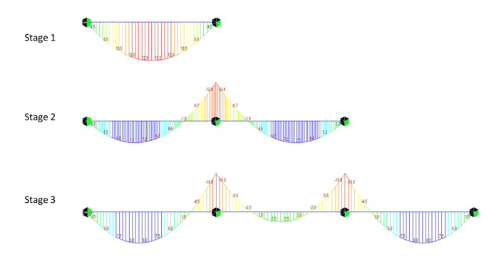
Basically, it’s just like taking each moment diagram conventionally based on each configuration. The sample model is also available for download if you want to try it for yourself the difference between the Accumulative and Independent Construction Stage Analysis.


.png)