Get Started midas Civil
 Featured blog of this week

Please fill out the Download Section (Click here) below the Comment Section to download the Complete Guide to Composite Sections
P Delta Analysis
Table of Contents
3. Code Provision as per IRC 112
4. P Delta Analysis in midas Civil
Please fill out the Download Section (Click here) below the Comment Section to download the Complete Guide to Composite Sections!
1. Concept
In recent studies, it is found that there are several structural problems to be addressed in bridges with tall piers. In cases of the piers with large heights the phenomena such as second-order effects, and P-Delta effects, shall be accounted for in the final design. The second-order effects are additional action effects caused by the interaction of axial forces and deflections under lateral load. First-order deflections lead to additional moments caused by the axial loads, and these, in turn, lead to further increases in deflection. Such effects are called P-Delta effects because additional moments are generated by the product of the axial force and element deflections.
P-Delta analysis is required when high vertical and lateral forces act simultaneously on a structure, causing first and second-order lateral displacement.
In other words, it is a nonlinear geometric effect of large direct stress acting upon transverse bending and shear behavior. The Compressive stress on structure makes it more flexible in transverse bending and shear, whereas tensile stress tends to stiffen members against transverse deformation.
2. Need for Analysis
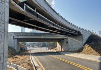
If the equilibrium condition is examined in the original configuration (using undeformed geometry), the moment at the base is M = VL, as shown in Fig. 1, and decreases linearly to zero at the loaded end. If equilibrium is considered for deformed configuration, the additional moment caused by axial force P acting on the transverse tip displacement Δ. The moment does not vary linearly along the length; the variation depends on the deflected shape. The moment at the base is now M = Vy - Px.
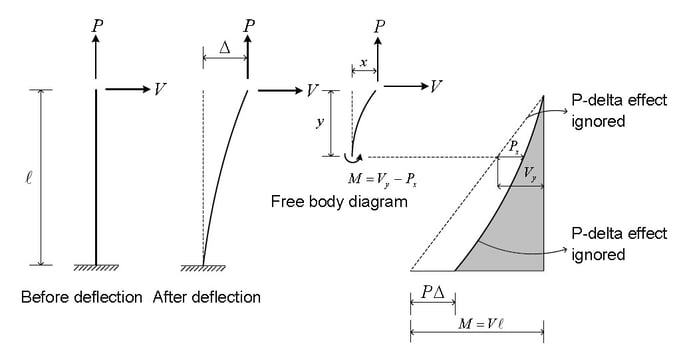
If the member is in tension, as shown in Fig.1, the moment at the base and throughout the member is reduced. Hence transverse bending deflection Δ is also reduced. Thus, the member is effectively stiffer against the transverse load V. Conversely, if the member is in compression, as shown in Fig.2, the moment at the base and throughout the member is increased. Hence transverse bending deflection Δ is also increased. The member is effectively more flexible against the transverse load V.
If the compressive force is too large, transverse stiffness goes to zero, and hence the deflection tends to infinity; at that point, the structure is said to have buckled.
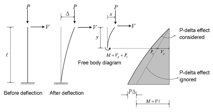
The P-Delta effect is subdivided into two, as shown in Fig. 3. The P-δ effect refers to the effect of the local geometry change, whereas P-Δ refers to the effect due to relative displacement between member ends.
The P-Delta analysis is particularly useful when the effect of gravity loads on the lateral stiffness of the structure is required to be checked. Certain codes (ACI318, AISC-LRFD) require analysis with the P-Delta effect to prevent the collapse of the structure due to secondary effects. This section describes the analysis of the Truss and target beam elements reflecting the P-Delta effect.
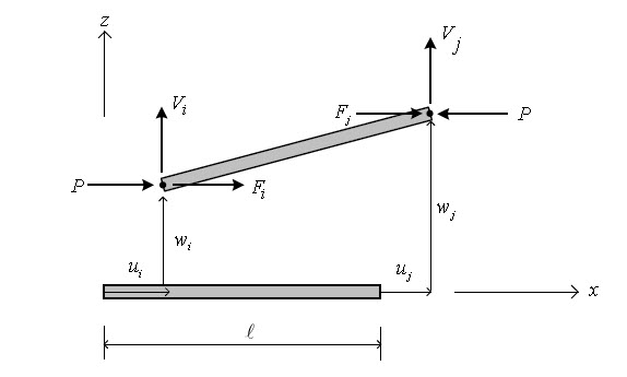
To reflect the P-Delta effect, a truss element is considered in a transformed state, and force equilibrium conditions are assumed.
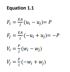
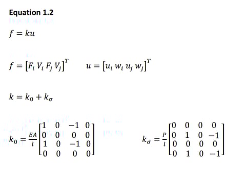
Where k0 represents a linear stiffness, ks represents geometric stiffness reflecting the P-delta effect. The axial force P, if in compression, has the negative sign. By applying the principle of virtual work, strain can be derived the same as eq. 1.2.
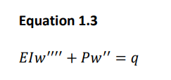
The concept of P-Delta analysis for beam element is the same as that for the truss element, only the point of difference being deformation of the element is considered additionally for beam. The load “q” being in the x-z plane has the equation described in finite element analysis, and the effect of the load can be given by equation 1.3.
To analyze induced bending deformation of beam element, strain equations can be used to obtain Eq.1.4 using the principle of virtual work.
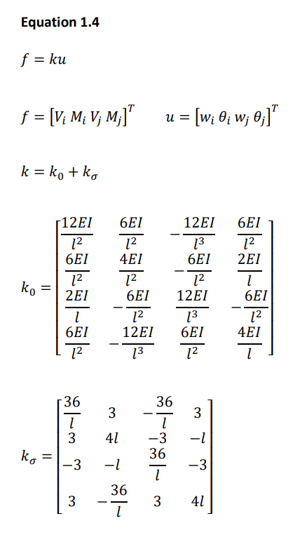
The following guidelines are given from the IRC112:2020 code for calculating the second-order effects.
Here we have explained the simplified criteria only. For other methods, we can refer to the concerned code.
Simplified Criteria for Second Order Effects
Slenderness criteria for isolated members (columns) of uniform cross-section
(1) Slenderness Ratio
The slenderness ratio λ is defined as le / i, where i is the radius of gyration of the uncracked concrete section. The effective length le is the length of a pin-ended column with constant axial force having the same cross-section and buckling load as the actual member.
(2) Second-order effects may be ignored if the slenderness ratio λ based on le as per Clause 11.2.2 of IRC 112:2020 based on the Effective length (height) of columns and piers is less than a certain value λlim as per Eq.1.5.
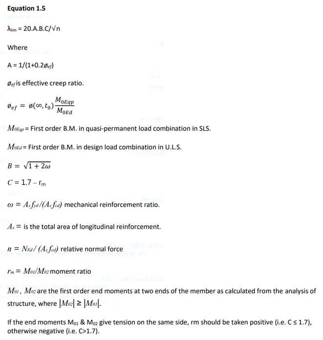
In the following cases, rm should be taken as 1.0 (i.e., C=0.7):
- For unbraced members in general.
- For braced members in which the first order moments arise predominantly from imperfections or transverse loading.
Note: For the initial dimensioning of members, simplified values of A =0.7, B =1.1, and C =0.7 may be
used.
(3) In the case of biaxial bending, the slenderness criterion may be checked separately for each direction. Depending on the outcome of this check, second-order effects (a) may be ignored in both directions, (b) should be taken into account in one direction, or (c) should be taken into account in both directions.
Following are the general steps to perform the P Delta Analysis in Midas Civil.
1. Linear static analysis is performed first.
2. Based on the member forces obtained from the first analysis, a new geometric stiffness matrix is formulated.
3. Static analysis is repeatedly performed, and the geometric stiffness matrix is repeatedly modified until the given convergence conditions are met.
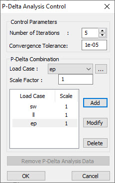
The P Delta Analysis Control is shown in Fig.5.
Control Parameters
Number of Iterations
Enter the number of iterations for the P-Delta analysis
Convergence Tolerance
Enter the convergence tolerance.
(Note: P-Delta Analysis and Buckling Analysis may not be used simultaneously. The use of P-Delta Analysis is limited to truss and beam elements.)
Let us discuss one of the FAQs on midas Civil regarding the P-Delta Analysis.
Question:
Which load cases do I have to add in “P-Delta Combination”? The result of the load combination, which doesn’t include a vertical load case, was changed after performing the P-delta analysis.
Solution:
The vertical (or gravitational) load cases should be added in the “P-Delta Combination” so that the program can find the modified stiffness matrix of the structure based on the geometric stiffness matrix due to the P-Delta load combination. Even if the lateral load case is added here, the results will remain the same because the lateral load will not make any axial forces in the case of a cantilever column.
For example, if we make a test model as below, all the three cases give the same results for P-Delta analysis as shown in the Fig.6.
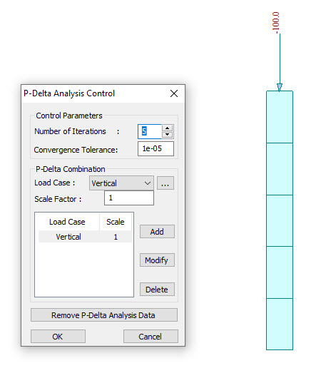 Case 1: Vertical Load
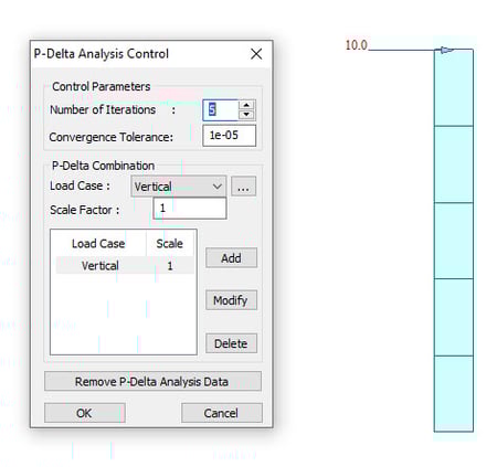 Case 2 : Horizontal Load
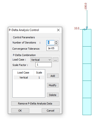
According to the information as mentioned above, in midas, P-Delta analysis will find the geometric stiffness matrix of structure due to the entered load cases in “P-Delta Combination”. This geometric stiffness matrix will be added to the elastic stiffness matrix to generate the modified stiffness matrix of structure, which will be applied to the analysis for all the load cases including lateral loads.
Additionally, when the user wants to see the 2nd order effect for multiple load combinations which have different load factors, the user has to modify the load case factor in “P-Delta Combination” and perform analysis again.
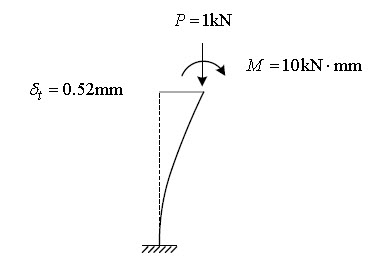
5. Illustrative Example
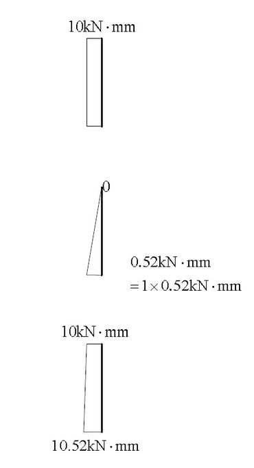
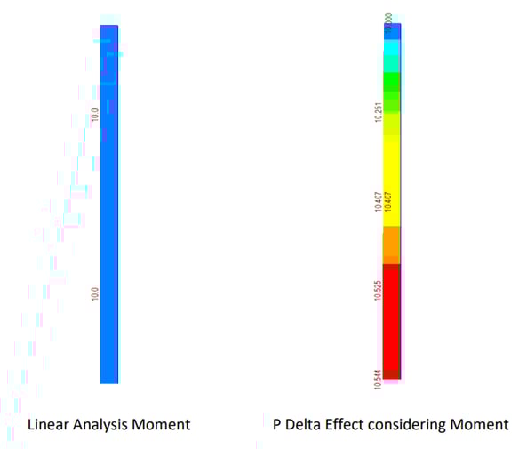
To understand the concept, we can consider one example for P Delta Analysis for cantilever column as shown in Fig. 7. In the first step, an analysis without P-delta effect is carried out to calculate the member force and deformation value, and then the additional moment by which the axial force is multiplied by the lateral displacement, that is, the P-delta moment as shown in the Fig. 8.
In Model 3, all degrees of freedom are constrained except the upper lateral displacement w1 and rotational deformation θ1, so the lateral displacement w1 and rotational deformation values θ1 can be estimated by the following method.
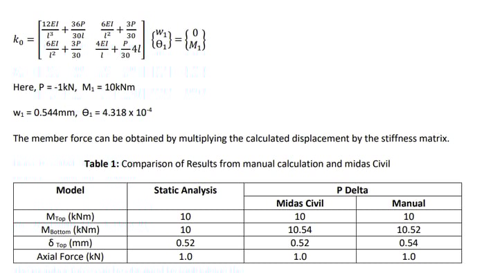
It is not easy to directly perform the analysis considering the P-delta effect by numerical calculation.
Therefore, If we add an additional P-delta moment to the force of the static analysis, the value close to
the moment due to the P-delta analysis can be obtained. The simple analytical equations are easy to
verify the forces getting from analysis programs such as midas Civil can be verified with manual
calculations as shown in Table 1


-1.png)