Get Started midas Civil
 Featured blog of this week

Table of Contents
1. Project Description
2. Determining Factors
3. Construction Process
4. Project Application in midas Civil
1. Project Description
Project Name: Manyovu Bridge
Type of Bridge: Continuous Slab Bridge
Location: Tanzania-Burundi Boarder
Company: Kaburu Okelo Consulting Engineers Website: https://kaburuokelo.com/
Engineer: Alituha Brian
Types of analysis used: Moving load analysis, Static analysis
Programs used: midas Civil
Length: 30m
Keywords: Skewed, Curved, Slab Bridge, varying thickness.
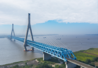
The Manyovi bridge is an overpass that connects Burundi and Tanzania. There was a need to separate their routes at the border post since both countries, Burundi and Tanzania, drive on different hands. Tanzanians keep left while Burindians keep right. The Manyovu Bridge is therefore a one-way road that helps to overcome such a contrariety.
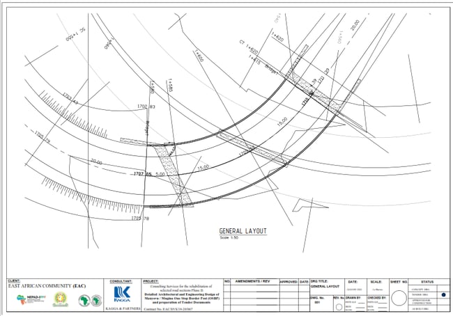
The bridge has two spans of 15 m each and a curvature radius of 600 m. The 600 mm thick center pier has a skew angle of 66.34° and a length of 6.7 m. The height of the pier is 6m. To house the 5 bearings above the pier, there is a 1 m wide and 1.2 m deep pier cap tapering, on both cantilevered ends, for 1.82m. Different skew angles of 7° and 55.14° were applied to each supporting abutment.
The Reinforced Concrete Slab Bridge has a varying thickness of 800.00 mm at the mid-span and 950.00 mm at the support with tapering of 1.50 m on each side of the center pier. The width is 11.00 m to accommodate two roadways (2x4.0m), two sidewalks (2x1.5m), and concrete barriers on an upstand (2x0.4m). It has a 9% vertical gradient and 8% superelevation. The superelevation helps to counteract the centrifugal force due to moving loads at the sharp curvature throughout the length of the bridge.
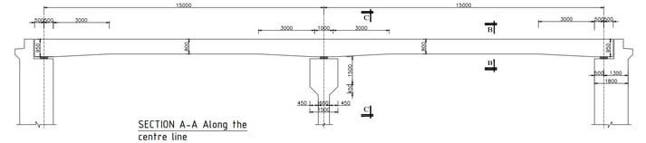 Figure 2. Longitudinal section
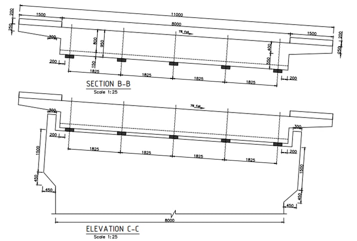 Figure 3. Cross-section
The design working life was chosen in accordance with the Eurocode EN 1990:2002 Cl 2.3(1).
2. Determining Factors
The bridge exhibits a huge curve and a generous skew angle which makes it impractical to use girders for the bridge deck. There are two types of slab bridges, viz. the Solid Slab Bridge and the Voided Slab bridge. Due to the high skew and curvature, the Solid Slab Bridge was meticulously chosen.
The alignment of the bridge was set considering the rugged terrain and sharp slopes all around the bridge. The collision loads and centrifugal forces had been among the major factors for bridge design.
Other advantages of using a slab bridge are:
- Conventional concrete and formwork are less costly.
- A smaller thickness of the deck reduces the height of fill and consequently the cost of the approaches.
- Improved aesthetics due to a flat soffit.
- A simple arrangement of reinforcement to avoid rebar clashes as they are evenly distributed throughout the full width of the deck.
- Placing concrete is much easier. The chances of honeycombing in concrete are less likely.
- Quicker construction at times.
Disadvantages of using slab bridges:
- The greater cost of materials
- Larger dead loads
3. Construction Process
Due to the curvature and skew it was decided that conventional concrete will be cast-in-situ. The formwork setting has to be versatile and shall fit the shape of the tapering slab. Connectors and push-pull props are used to join the walers to give the required shape to the formwork. The slab concreting work procedure involves construction joints, concrete production, pouring of concrete, finishing the surface, and curing of concrete.
With all the formwork settings, the contractor must take care of the bracing and safety items.
4. Project Application in midas Civil
Due to the different skew angles on either side of the bridge and the high curvature, modeling of the bridge was quite demanding. CAD importing and modeling features were used to achieve the final outcome.
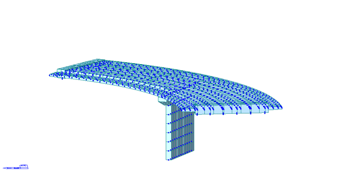 Figure 4. Nodes/elements used for bridge modeling
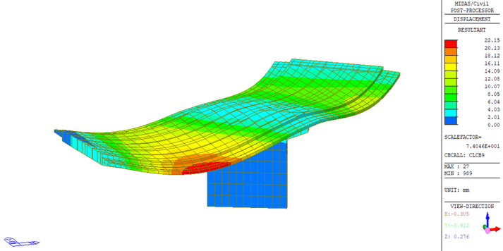 Figure 5. Bridge deformation under critical load combination
The structural analysis has been carried out based on the global analysis model established by using the structural analysis software of midas Civil.
Different load combinations were carried out using the above-mentioned bridge loads and reactions of these actions were directly produced by the software.
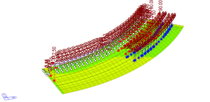 Figure 6. Moving load tracer
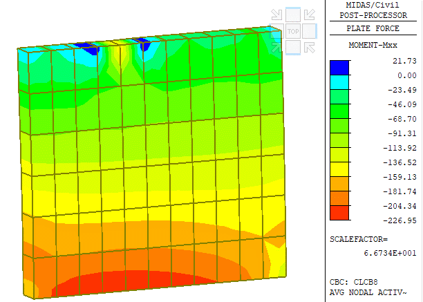 Figure 7. Plate forces for skewed pier
The plate forces for the skewed pier, as shown in Figure. 7, clarify the high moments about the vertical axis of the pier, which are majorly at the inner curvature. The critical load combination included the effect of self-weight, crash barrier, walkway, wearing surface as gravity loads and Wind load, Deck collision load as well as Collision Force on the Pier as lateral loads out of which the deck collision load caused significant negative moments at the pier bottom.


.png)