 Get Started midas Civil
 Featured blog of this week

How to Utilize AutoCAD in Geometry Modeling
Table of Contents
1. How to Import AutoCAD Drawings to midas Civil
2. Tips and Reminders
1. How to Import AutoCAD Drawings to midas Civil
Supposed you are given this cross-section of a bridge in AutoCAD, and you need to interpret this as a model in midas Civil:
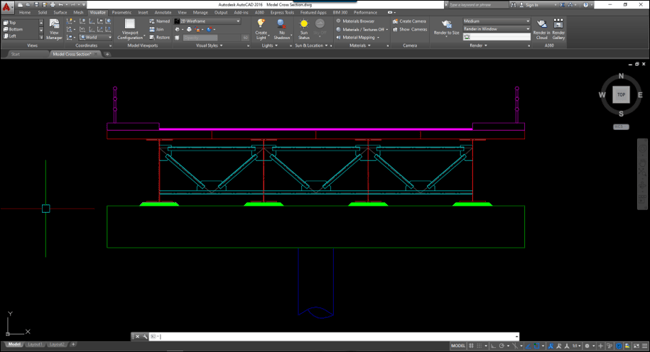
To most engineers, it is easier to interpret this cross-section to a bridge geometric model using AutoCAD, like this:
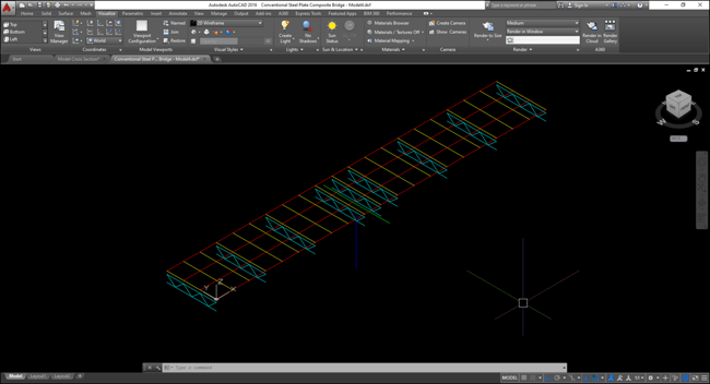 Figure 2. Sample bridge geometric mode
Since midas Civil is fully compatible with AutoCAD, you can directly use this drawing as your geometry model in midas Civil. Just simply save your drawing to a DXF (.dxf) file, then you can already import it to midas Civil.
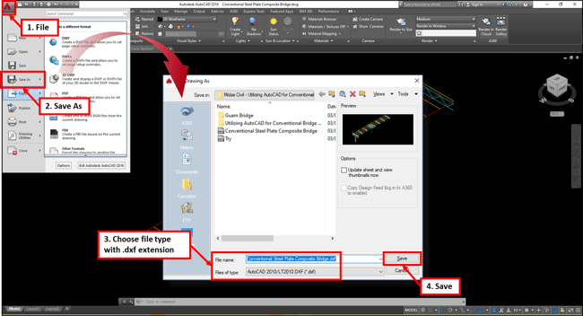 Figure 3. AutoCAD save as DXF file
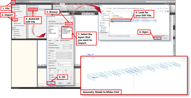 Figure 4. Import DXF file to midas Civil
And that easy, you now have the geometry model of your structure, ready to use in your midas Civil. But there are few things that you need to consider to use this method to draw your model. With this, we will also give some Tips and Reminders on how to effectively draw your model in AutoCAD.
2. Tips and Reminders
2.1 The first thing that you need to consider before importing your DXF file is to make sure that the active unit of measurement in your midas Civil is consistent with the unit of measurement that you considered in your drawing. For example, you have drawn in AutoCAD in millimeters, then the active unit of measurements in midas Civil should also be in millimeters before importing.
You can easily change the active unit of measurement in midas Civil using the functions available at the lower-right of the interface:
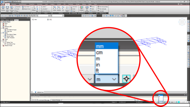 Figure 5. Active unit of measurement
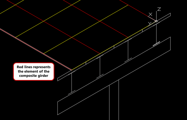
2.2 Draw your elements in AutoCAD considering the section offset that you will use in midas Civil. For example, you will consider the offset of a steel composite section on the center-top, then, you should draw the element that will represent your girder in AutoCAD at center-top as well.
2.3 Set different layers for each structural component since midas Civil will adapt these layers as Structural Groups. This is useful especially when you are going to define Construction Stages on your model since you no longer need to define these groups one by one anymore. You can also consider creating different layers with the consideration of the launching stage already.
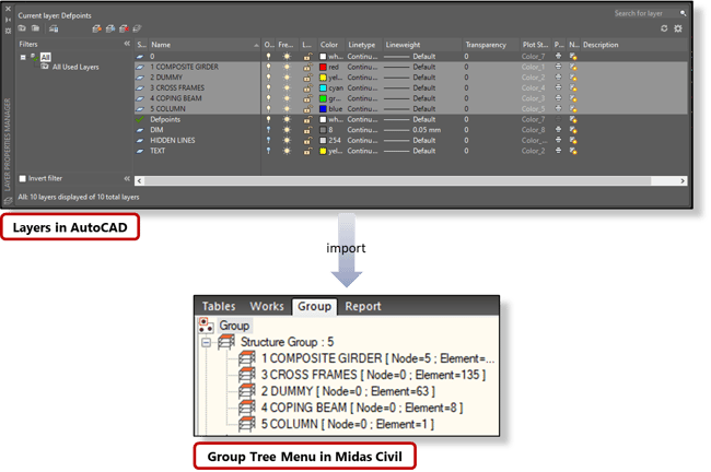 Figure 7. AutoCAD layers- midas Civil Structure Group
2.4 The direction on how you draw in AutoCAD will also be the basis of your element’s local axis and local direction in midas Civil.
2.5 Midas Civil will also follow the World UCS of your AutoCAD for the coordinates of your nodes and elements. Since when drawing in AutoCAD in 3D, you need to move your origin from time to time to draw on different planes. With this, no matter what active coordinate system that you are in, midas Civil will always follow the world UCS. It is highly suggested to locate a reference point of your model on the origin of the World UCS for easier navigation once you import to midas Civil.
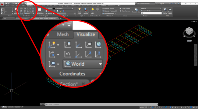 Figure 8. AutoCAD Coordinate System
2.6 Additional things to consider when drawing in AutoCAD:
2.6.1 Polylines and Lines in AutoCAD will be imported as beam elements.
2.6.2 Rectangular enclosed Polylines will be imported as plate elements.
2.6.3 3-points Arcs will be imported as beam elements considering the end-to-end nodes only. It is advisable to divide your arcs into multipoint arch before importing.
2.6.4 Solids cannot be imported from AutoCAD to midas Civil.
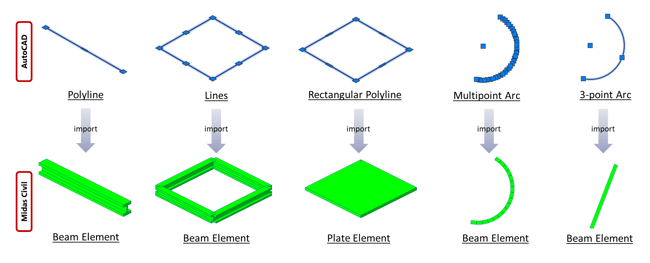 Figure 9. Element type comparison
Sample DXF file is also downloadable on this article so you can try practicing how to import your drawing from AutoCAD to Midas Civil.


.png)

/2020%20Pics%20for%20drafts/Moving%20Load%20All%20You%20Need%20to%20Know-1.jpeg)
/MC%2004%20Section/How%20to%20Define%20Section%20Properties%20in%20Various%20Bridge%20Design%20Conditions%20345%20240.png)
/345%20240/Application%20of%20Links%20in%20Bridge%20FE%20Models.png)