Would you like to sign out?
Bridge

Integral Bridge

1. What is Integral Bridge?

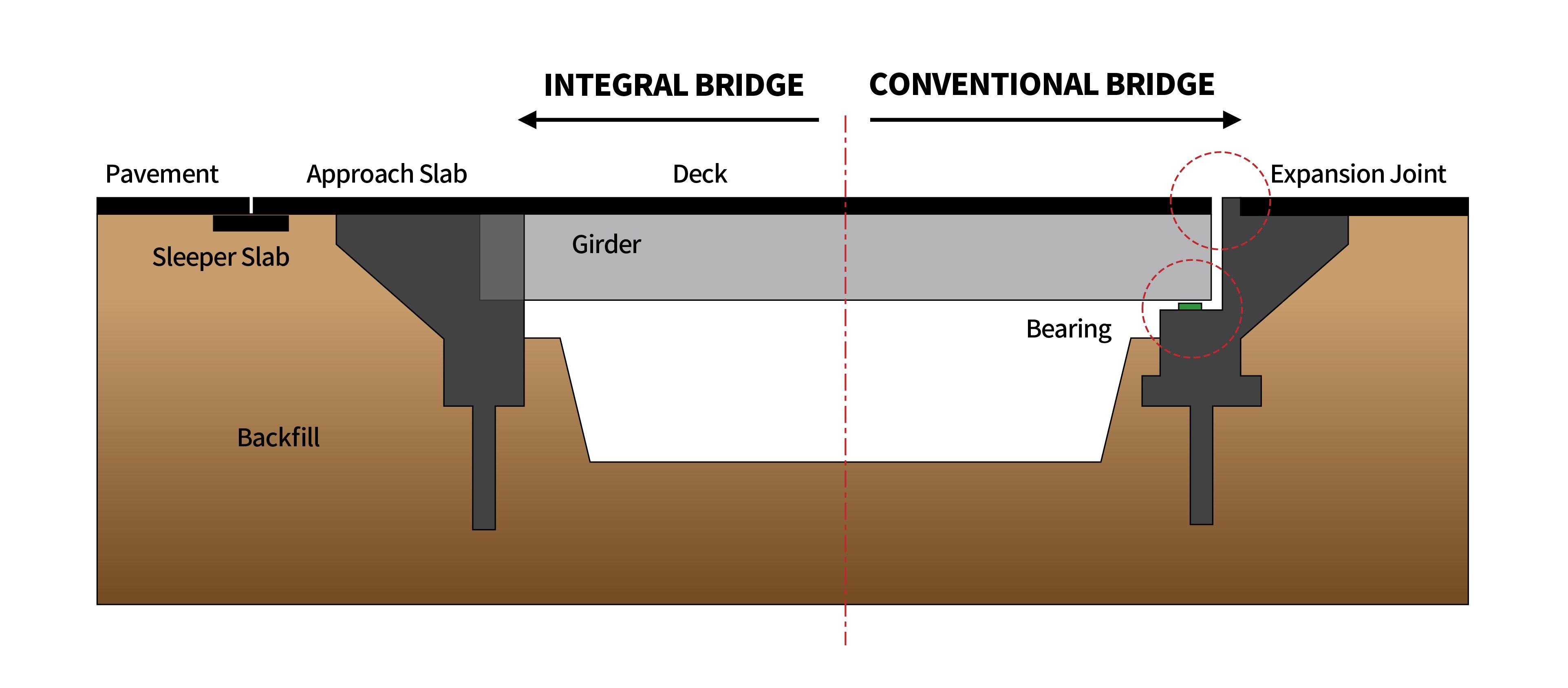
An integral bridge refers to a bridge in which the superstructure and the pier/abutment are integrated out of necessity. The integration between the superstructure and substructure implicates that there is no bearing that transmits force or displacement between the two structures.

Bridges in which the pier and the superstructure are integrated together are often used when the construction method is determined by the required span length. For example, they are structural systems used for long span bridges constructed with the balanced cantilever method (or free cantilever method, FCM). Since the pier and the superstructure are rigidly connected (rigid frame), it is difficult to accurately consider problems arising from external and internal factors in the design stage of integral bridges, but they are still steadily being used because of the advantages of FCM.

  • Fig. Integral Pier Bridge (Brisbane Gateway Bridge)

Expansion joints and bearings play an important role in bridge maintenance. Therefore, in order to eliminate problems that may occur during bridge maintenance as well as increasing structural efficiency, bridges in which abutments and superstructures are integrated are used. These types of bridges are referred to as integral bridges (integral abutment bridges).

  • Fig. Integral bridge and conventional bridge

Integral bridges have the advantage over conventional bridges due to their easy maintenance and reduced cost. This is possible because some bearings and expansion joints are removed. Furthermore, the elimination of expansion joints not only improves ride comfort, but also improves durability because rain, snow, and chloride cannot penetrate the substructure.

  • Fig. Expansion joint

Some features of integral bridges include:


  - Applicable to both concrete and steel bridges.

  - Displacement caused by thermal expansion and contraction is directly transmitted to the abutments and pile foundations,

    so displacement limitation is required.

  - Accurate evaluation is difficult because interaction between the abutment and the soil surrounding the structure is complex.

  - For concrete girders, the effects of creep and shrinkage should be considered.

  - Material and construction method of the backfill on the back of the abutment are important.

  - Precast girders can be used, but the reinforcement detail for moment connection as well as

    the beam-end rotation due to creep and shrinkage must be considered.


Additionally, geometric design standards such as the span length, skew, and height of abutment, as well as regional design conditions for temperature gradient, seismic, and moving loads must be considered.

  • Fig. Integral bridge

2. Types of Integral Bridge

Different types of integral bridges can be used depending on the location of the bridge, the structural type, and the characteristics of the soil. The four most representative integral bridges are as follows:

  • Fig. Types of integral bridge

A. Frame Abutment

  - In comparison to the other types of integral bridges, frame abutments have a higher abutment wall. The Frame abutment is integrated

    with the superstructure, forming a portal frame structure that can effectively support loads.

  - The horizontal earth pressure increases as the high of the abutment increases. Therefore, for frame abutments, the horizontal earth pressure of the backfill is large compared to other types of integral bridges.

B. Bank pad abutment

  - If the ground on the slope where the abutment is installed is high, bank pad abutments can be used because a high wall is not required.

  - If pile foundations are not used, bank pad abutments must be able to accommodate sliding due to thermal expansion and contraction as well as rotation due to deck beam bending at the interface between the structure and the ground.

C. Embedded wall abutment

- Like Frame abutments, embedded wall abutments are full height reinforced concrete integral bridge types.

  - Embedded walls are installed under the retained fill just like diaphragm walls.

  - Due to the high stiffness of the wall, it can withstand large earth pressure and can prevent ground subsidence.

D. Flexible support abutment

  - A method made to efficiently resist temperature changes transmitted to the pile foundations

    or resist displacements caused by the longitudinal direction forces.

  - A method of placing precast concrete holes(sleeves) around the piles to secure space for displacement.

  - In order to use a flexible support system for the bank pad abutment, reinforced earth retaining walls are placed in front or behind the abutments.


An example of the structural analysis model for Integral Bridge design is shown in the figure below.

  • Fig. Structural analysis model for integral bridge

3. Semi-Integral Bridge

Semi-integral abutment bridges, also know as end screen abutments, are designed to take full advantage and compensate the disadvantages of integral bridges, but differ in their structural system. For this particular type of bridge, the deck is integrated with the abutment wall, but not with the girder (ex. concrete beam, steel beam). Since a bearing system that can accommodate horizontal displacement is used to support the girder, the superstructure and substructure do not move as one.

Semi-integral bridges can be used for both frame abutments and bank pad abutments.

  • Fig. Types of semi-integral bridge

콘텐츠가 도움이 되셨나요? Did you find the content helpful?
To List
Table of Contents

Stay Updated on bridge Issues.