B. Lane Factors
The Simultaneous Loading Factor is a coefficient introduced based on the fact that the probability of simultaneous loading of a design vehicle load on two or more lanes is relatively small compared to that of a single lane. In order to take this into account in Japan, the UK, and the Eurocode, the magnitude of the vehicle loads is different for the main loading lane and longitudinal loading lane. On the other hand, in Korea, the United States, and Canada, vehicle loads of the same magnitude, multiplied by the simultaneous loading factor, are applied to all loading lanes. This same principles also applies to the loading of Pedestrian Loads.
Since the probability that the vehicle load and pedestrian load are simultaneously loaded is relatively small compared to the case where only the vehicle load is loaded, it is reasonable to apply the simultaneous loading factor even if the pedestrian load and the vehicle load are included at the same time.


/10.%20Moving%20Load/Figure/Moving%20Load%20Analysis_figure_Example%20of%20design%20truck%20load.jpg)
/10.%20Moving%20Load/Figure/Moving%20Load%20Analysis_figure_Example%20of%20design%20lane%20load.png)
/10.%20Moving%20Load/Figure/Moving%20Load%20Analysis_figure_A%20train%20above%20a%20railway%20road,%20Train%20load%20in%20design%20codes-1.png)
/10.%20Moving%20Load/Figure/Moving%20Load%20Analysis_figure_Pedestrian%20load.jpg)
/10.%20Moving%20Load/Figure/Moving%20Load%20Analysis_figure_Special%20vehicle%20loads.jpg)
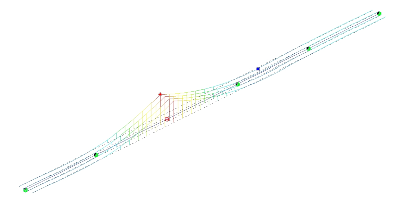
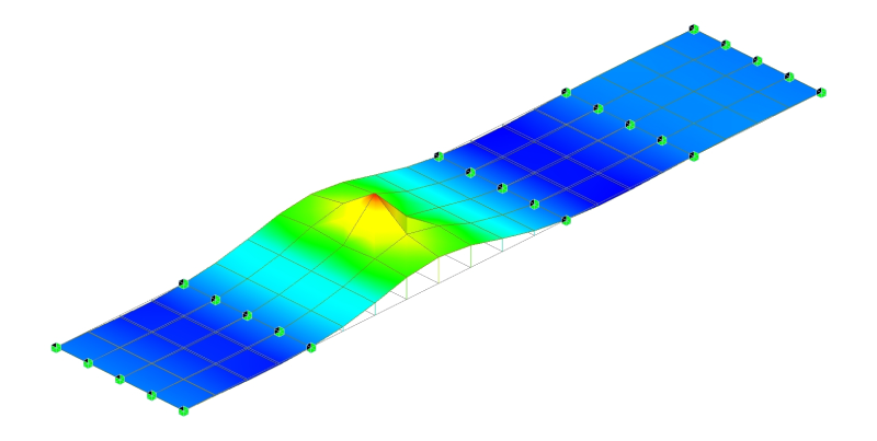
/10.%20Moving%20Load/Figure/Moving%20Load%20Analysis_figure_Moving%20load%20analysis%20for%20bridges.png)
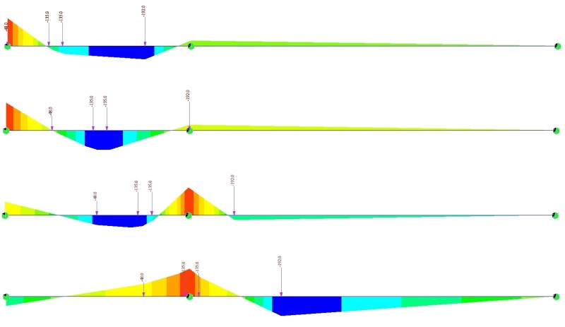
/10.%20Moving%20Load/Figure/Moving%20Load%20Analysis_figure_Calculation%20of%20maximum%20minimum%20moment%20using%20the%20Influence%20lines.png)
/10.%20Moving%20Load/Figure/Moving%20Load%20Analysis_figure_Comparison%20of%20results%20between%20full%20loading%20case%20and%20alternate%20loading%20case.png)
/10.%20Moving%20Load/Figure/Moving%20Load%20Analysis_figure_Enveloped%20results%20and%20corresponding%20results.png)
/10.%20Moving%20Load/Figure/Moving%20Load%20Analysis_figure_Number%20of%20notional%20lanes.png)
/10.%20Moving%20Load/Figure/Moving%20Load%20Analysis_figure_Multi%20lane%20loading%20factor%20example.png)
/10.%20Moving%20Load/Figure/Moving%20Load%20Analysis_figure_Vertical%20loads%20of%20traffic%20loads%20in%20Eurocode.png)
/10.%20Moving%20Load/Figure/Moving%20Load%20Analysis_figure_Groups%20of%20traffic%20loads%20in%20Eurocode.png)
/10.%20Moving%20Load/Figure/Moving%20Load%20Analysis_figure_Vertical%20loads%20of%20traffic%20loads%20in%20AASHTO%20LRFD.png)
/10.%20Moving%20Load/Figure/Moving%20Load%20Analysis_figure_Dynamic%20Allowance%20presented%20by%20the%20AASHTO%20LRFD.png)
/10.%20Moving%20Load/Figure/Moving%20Load%20Analysis_figure_Additional%20Dynamic%20Amplification%20presented%20by%20the%20Eurocode.png)
/10.%20Moving%20Load/Figure/Moving%20Load%20Analysis_figure_Centrifugal%20Force.png)
/10.%20Moving%20Load/Figure/Moving%20Load%20Analysis_figure_Braking%20and%20acceleration%20force.png)
/10.%20Moving%20Load/Figure/Moving%20Load%20Analysis_figure_Fatigue%20failure%20of%20the%20bridge.jpg)