Get Started midas Civil
 Featured blog of this week

Bridge Rating in Midas
Table of Contents
1. Purpose of Bridge Rating
2. Load Rating Levels
3. Bridge Rating Parameters
4. Composite Section Data
1. Purpose of Bridge Rating
Bridge load rating provides a standardized procedure to determine the safe load-carrying
capacity of a bridge, thereby allowing engineers to establish posting and permitting
requirements. The structural condition of components, material properties, loads, and traffic conditions all contribute to the load rating, which describes the capacity of the controlling component of the structure. The primary purpose of bridge load rating is to ensure public safety.
Bridge load rating provides a measure of a bridge's ability to carry a given live load in terms of a simple factor, referred to as rating factor. These bridge rating factors can be used to aid in
decisions about the need for (1) load posting, (2) bridge strengthening, (3) overweight load
allowances, and (4) bridge closers.
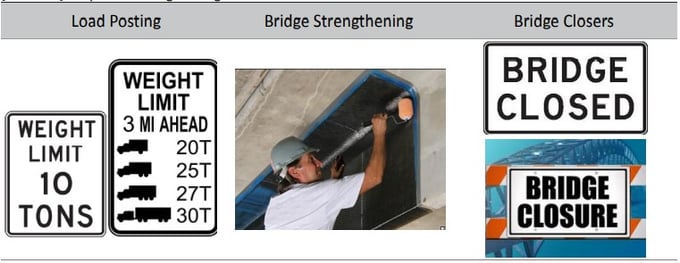
Figure.1 Purpose of Bridge Rating
Load ratings are expressed as a rating factor (RF) or as a tonnage (for legal and permit vehicles only) for a particular vehicle. The emphasis in load rating is on the live-load capacity and dictates the approach of determining rating factors instead of the design approach of satisfying limit states.
2. Load Rating Levels
Midas Civil supports the LRFR Load Rating Design using Part A only. This LRFR methodology consists of three distinct levels of evaluation:
(1) Design load rating
(2) Legal load rating
(3) Permit load rating
2.1 Design Load Rating
The design load rating is a first-level assessment of bridges. It is a measure of the performance of existing bridge to current LRFD bridge design standards.
(a) Live Load
At the Design load rating level, the HL-93 live-load model of the LRFD is applied, using dimensions and properties of the bridge in its present inspected condition.
(b) Limit States
Under this check, bridges are screened for the strength limit state at the LRFD design level
of reliability. Evaluation at a second lower evaluation level of reliability is also an option.
The rating also considers all applicable LRFD serviceability limit states
(c) Purpose
Design load rating can serve as a screening process to identify bridges that should be load
rated for legal loads.
Bridges that pass the design load check (RF≥1) at the Inventory level will have satisfactory
load rating for all legal loads that fall within the LRFD exclusion limits.
(d) Level of Design Load Rating
There are two levels of the Design Load Rating:
i) Inventory Rating Level
The Inventory rating level generally corresponds to the rating at the design level of reliability for new bridges in the AASHTO LRFD Bridge Design Specifications but reflects the existing bridge and material conditions with regard to deterioration and loss of section.
Load ratings based on the Inventory level allow compressions with the capacity for new structures and, therefore, result in a live load, which can safely utilize an existing structure for an indefinite period of time.
ii) Operation Rating Level
Load rating based on the Operation rating level generally describes the maximum permissible live load to which the structure may be subjected. Generally, corresponds to the rating at the Operating level may shorten the life of the bridge.
2.2 Legal Load Rating
This second-level rating provides a single safe load capacity (for a given truck configuration) applicable to AASHTO and State legal loads. The Previous distinction of Operating and Inventory level ratings is no longer maintained when load rating for legal loads. Legal load rating provides a level of reliability, corresponding to the operating level reliability for redundant bridges in good condition.
(a) Live Load
Live load is categorized into the two types according to AASHTO LRFR 2011 as:
1) AASHTO Legal loads, as specified in Article 6A.4.4.2.1a
2) The Notional Rating Load as specified in Article 6A.4.4.2.1b or State legal loads.
(b) Limit States
Strength is the primary limit state for load rating; service limit states are selectively applied.
(c) Purpose
Bridges that do not have sufficient capacity under the design-load rating shall be load rated for legal loads to establish the need for load posting or strengthening.
2.3 Permit Load Rating
This third level of rating should only be applied to bridges having sufficient capacity for legal loads. In other words, Permit load rating should be used only if the bridge has a rating factor greater than 1.0 when evaluated for AASHTO legal loads.
(1) Live Load
The actual permit vehicle’s gross vehicle weight and axle configuration will be the live load used in the permit-load evaluation. The MBE (Manual for Bridge Evaluation) categorizes permit loads into two classes:
1) Routine/annual permits, and
2) Special permits.
(2) Limit States
Permits are checked using the Strength II limit-state load combination with the Service II limit-state load combination optional for steel bridges to limit potential permanent deformations.
(3) Purpose
Permit load rating checks the safety and serviceability of bridges in the review of permit application for the passage of vehicles above the legally established weight limitations.
3. Bridge Load Rating Parameters in Midas
 Figure 2. Rating Tab
3.1 Rating > Bridge Rating Design > Steel Design> Rating Design Code
- The program performs the load rating based on the code selected in this dialog box.
3.2 Rating > Bridge Rating Design > Steel Design> Rating Parameters
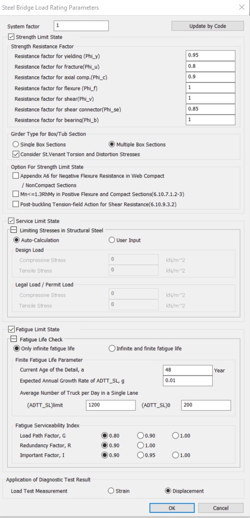 Figure 3. Load Rating Parameters Dialog Box
(1) The system factor (≤1.2) can be inputted. The system factor is multiplied by the flexural strength (Mn) and shear strength (Vn) and, therefore, applied to all elements.
(2) Strength Resistance Factor Strength Resistance Factor is defined. The resistance factors are automatically set to the default values defined in AASHTO LRFR 12. The values also may be modified or entered manually.
(3) Girder Type for Box/Tub Section > Consider St. Venant Torsion and Distortion Stress
If the Multiple Box Section option is selected, St. Venant Torsion and Distortion Stress can be optionally considered since they may be neglected when the relevant conditions (Article 6.11.2.3) are satisfied.
However, if Single Box Section option is selected, St. Venant Torsion and Distortion Stress are automatically considered. The value of distortion stress is determined based on the input value of "Warping Stress Range" option in Fatigue Parameter.
(4) Options for Strength Limit State
- Appendix A6 for Negative Flexure Resistance in Web Compact/Noncompact Sections If this option is checked, Appendix A6 is applied for the flexural strength of straight composite I-sections in negative flexure with compact/noncompact webs.
- Mn≤1.3RhMy in Positive Flexure and Compact Sections(6.10.7.1.2-3) If the three conditions below are not satisfied for the compact sections under positive flexure in a continuous span, the Mn value is restricted to 1.3RhMy.
- The span under consideration and all adjacent interior pier sections satisfy the requirements of Article B6.2,
- The appropriate value of θRL from Article B6.6.2 exceeds 0.009 radians at all adjacent interior-pier sections - In which case the nominal flexural resistance of the section is not subject to the limitation of Eq. 6.10.7.1.2-3.
- Post-buckling Tension-field Action for Shear Resistance (6.10.9.3.2)
- If this option is checked, post-buckling resistance due to tension field action is considered in the nominal shear resistance of an interior stiffened web panel according to AASHTO LRFD 19.
(5) Service Limit State If this option is checked, the service limit is verified according to AASHTO LRFR 2011 6A.6.4. If Auto-Calculation is selected, the limiting stresses are automatically calculated as follows:
Design Load: fR = 0.95 RhFyf
Legal/Permit Load: fR = 0.95 Fyk
If User Input is selected, the limiting stresses can be manually inputted for design load and legal/permit load respectively. The allowed compressive stress and tensile stress of the steel girder need to be inputted.
(6) Fatigue Limit State If this option is checked, the program checks the Fatigue Limit State according to AASHTO LRFR 19 6A.6.4.
(7) Application of Diagnostic Test Result Adjustment factor resulting from the comparison of measured test behavior with the analytical model can be calculated. Select between Strain and Displacement obtained from the diagnostic test. Measured value can be entered in Diagnostic Test Results menu.
3.3 Unbraced Length ▶ Rating > Bridge Rating Design > Steel Design> Unbraced Length
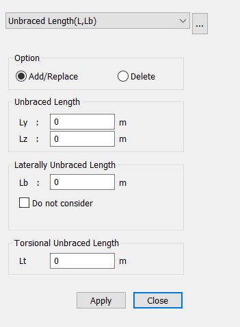 Figure 4. Unbraced Length Dialog Box
The Unbraced Length for steel composite section can be entered to calculate lateral torsional buckling resistance in compression flange of I Girder or top flange of Tub Girder. If the lateral unbraced length is not inputted, the program will use span lengths entered in Span Information. If Span Information was defined either, the lateral unbraced length is applied as the corresponding element length.
3.4 Fatigue Parameter ▶ Rating > Bridge Rating Design > Steel Design> Fatigue Parameter
(1) Category Category defined by 75yr-(ADTT)SL equivalent to infinite life (Table 6.6.1.2.3-2).
(2) (ADTT)SL Number of trucks per day in a single-lane averaged over the design life (3.6.1.4.2) Value can be manually calculated as per 3.6.1.4.2-1.
(3) Number of cycles per truck passage Value can be taken from Table 6.6.1.2.5-2.
(4) Warping Stress Range For the verification of fatigue, flexure stress is calculated as the summation of Longitudinal Bending Stress Range and Longitudinal Warping Stress Range. By choosing the Auto-Calculation option, fatigue vertical bending moment is simply increased by 10% for the longitudinal warping stress.
If the User Input option is selected, longitudinal bending stress range is summated with the inputted value of the Longitudinal Warping Stress Range for top or bottom flange depending upon the flexure condition at the section. These distortion stresses are considered only for the sections having box flange as those are the section in which the torsion is considered
3.5 Rating > Bridge Rating Design > Steel Design> Curved Bridge Info
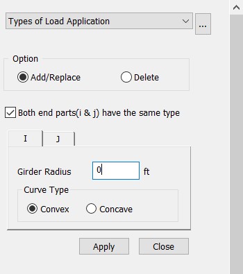 Figure 6. Curved Bridge Information Dialog Box
Once the girder radius value of the element units in the steel composite section is entered, the corresponding elements are categorized as curved bridges.
(1) Radius is used for the review of shear connector's pitch and the moment of inertia of area for the longitudinal stiffener attached to web.
(2) Curve Type - Convex, Concave If Convex is selected, Left Stiffener is on the side of the
web away from the center of curvature and Right Stiffener is on the side of the web toward the center of curvature. If Concave is selected, the opposite case of the convex is applied. The Left and Right are determined based on the progressing direction of the cross-section.
3.6 Rating > Bridge Rating Design > Steel Design > Diagnostic Test Result
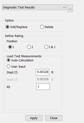 Figure 7. Diagnostic Test Result Dialog Box
Diagnostic Test Result Adjustment factor resulting from the comparison of measured test behavior with the analytical model can be considered to calculate the load-rating factor based on the test result.
(1) Auto calculation
Deflection and Kb are inputted manually for the diagnostic test to calculate adjustment factor.
(2) User Input
The Adjustment Factor, K, is inputted by users. K is used to calculate the factored load-rating factor.
K = 1+ Ka.Kb (8.8.2.3.1-1)
where, Ka : accounts for both the benefit derived from the load test, if any, and consideration of the section factor (area, section modulus, etc.) resisting the applied test load Kb: accounts for the understanding of the load test results when with those predicted by theory.
Refer to the Table 8.8.2.3.1-1 of The Manual for Bridge Evaluation, 2011
3.7 Design Material Data
Rating > Bridge Rating Design > Steel Design> Rating material
In this dialog box, the Material Properties can be modified for the calculation of the structure capacity. The material utilized for composite sections is provided in the SRC material properties.
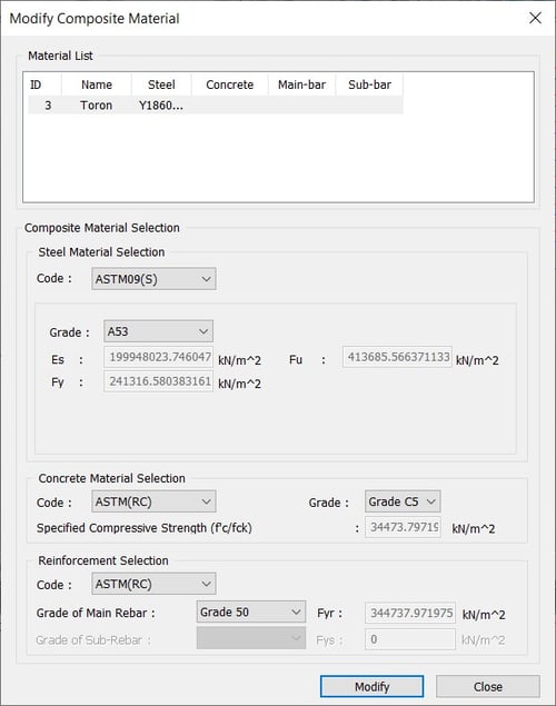 Figure 8. Rating Material Dialog Box
(1) Modify Composite Material
This dialog box is used to input material characteristics for the steel composite section design. The material property values entered will have a priority over the values entered in Material Data dialog box.
1) Steel of the Steel Girder Section
Hybrid Factor Hybrid Factor is considered in the case where flanges and web have different material properties.
2) Concrete of the Concrete slab
3) Steel Rebar of the Concrete slab
3.8 Setting for Load Rating
In this section, we define the condition factor and the part of the structure for which the load rating is performed.
Rating > Bridge Rating Design > Steel Design> Rating Group Setting
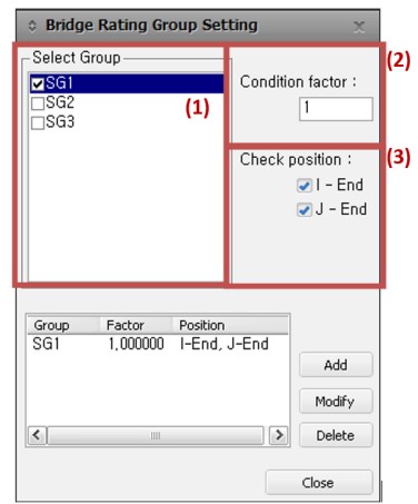 Figure 9. Rating Group Setting Dialog Box
The Bridge Rating Group Setting Dialog allows users to apply Condition Factors per different groups defined already and i- and j-end check positions.
(1) Selected Groups are targeted for the design of the Rating Factor. Structural groups composed of SRC material properties are shown in the list after performing an analysis.
(2) Different values of Condition Factor, 𝝋𝒄, can be applied to different Structure Groups of elements. In the program, the Condition Factor is internally multiplied to Nominal Flexural Strength/Resistance, Nominal Shear Strength and Nominal Fatigue Resistance to calculate the Load Factor.
(3) The Check Position, i- and/or j- end, is considered and selected for the Groups selected for the design.
3.9 Definition of Rating Case
Rating > Bridge Rating Design > Steel Design> Define Rating Case
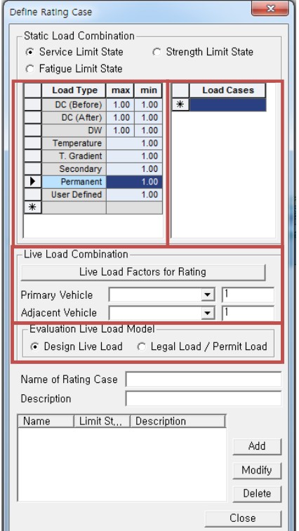 Figure 10. Define Rating Case Dialog Box
In Define Rating Case Dialog, Load Factor is defined for each of the Service Limit State, Strength Limit State and Fatigue Limit State.
(1) For the Fatigue Limit State calculation, only live load can be selected.
(2) Maximum and minimum Load Factors for each Load Type (DC, DW, ...) can be manually modified. Only one load factor is inputted for the Temperature Load, but the load factor is used as positive and negative (+, -) for the calculation.
(3) DC(Before) is a dead load of structural components and non-structural attachments for the state before the concrete deck is activated. When the construction stage is defined in the model file, the program automatically takes DC(Before) as the dead load right before the composite action.
DC(After) is a dead load of structural components and non-structural attachments for the state after the concrete deck is activated. DC(After) considers the Erection load case, if defined by user, and the stress caused by the time-dependent material property, Creep & Shrinkage.
(4) Per different Load Type, Load Cases can be additionally inputted in the different Load Type and reflected in the Load Rating Factor calculation. Information inputted in the Load case internally generates the 12 Types concurrent results (Fxmax, FX-min, Fy-max ... Mz-min).
(5) Live Load and Load Factor are inputted separately for the Primary Vehicle and Adjacent Vehicle. When it is clicked, the load combinations and corresponding Load Factors are generated. When the vehicle is clicked, the load factors are inputted in the Rating Case Dialog Box.
(6) Each Live Load should be inputted prior in Moving Load Cases at: ▶Load > Load Type > Moving Load > Moving Load Analysis Data > Moving Load Cases
(7) Evaluation Live Load Model Load Rating flow as per LRFR standard is explained in [Fig.3.2]. In this Live Load Factors for Rating Dialog, rating level needs to be defined to apply the limiting stresses of the corresponding vehicle load in Service Limit State.
4. Composite Section Data
Steel composite section is composed of steel girder and concrete slab. Additional stiffeners may be arranged in the steel girder; longitudinal and sub reinforcement rebars may be arranged in the concrete slab. In this section, Steel Composite Load Rating features and functions and related section input method and design variables are explained.
For defining Longitudinal Reinforcement,
Rating > Bridge Rating Design > Steel Design> Longitudinal Reinforcement
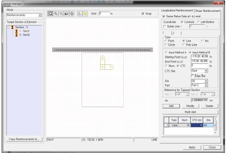 Figure 11. Section Manager Dialog Box
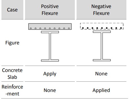 Figure 12. Positive and Negative Flexure
Transverse Stiffener
Rating > Bridge Rating Design > Steel Design> Transverse Stiffener
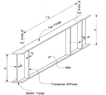 Figure 13. Transverse Stiffener
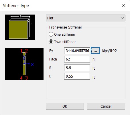 Figure 14. Stiffener Type Dialog Box
1) Stiffener Type
2) One / Two Stiffener Option Button
Choose between one or two stiffeners. The two stiffener option is available for I/Box/Tub sections.
3) Pitch (do)
Pitch refers to the Transverse Stiffener spacing. At the strength limit state, this can be used to distinguish between stiffened and unstiffened webs or calculate shear strength of the web.