 Get Started midas Civil
 Featured blog of this week

When a static concentrated load is applied on a deck, the deck will deflect transversely as well as longitudinally, similar to the structural behavior of a two-way slab. The load distribution becomes more complex when multiple point loads are applied to the deck, such as truck loads. When the structural model is simplified to a 2D frame model, it is important to obtain the resulting 3D forces from the 2D model.
Commonly, there are two ways of handling live load distributions in the transverse direction:
Approximate Method - AASHTO LRFD Article 4.6.2 presents an approximate method of analysis in which the deck is subdivided into strips perpendicular to the supporting elements (webs). Internal forces are determined first by structural analysis of a unit width of transverse cross-section and then by dividing these force and moment results by the width of the strip to determine forces per foot along the superstructure.
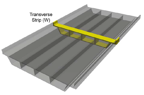
Equations for the width of the transverse strip in the longitudinal direction for cast-in-place concrete box girder bridges are:
-
Overhang: W = 45.0 + 10X
-
Positive Moment: W = 26.0 + 6.6S
-
Negative Moment: W = 48.0 + 3.0S
Where S = spacing of supporting components (ft)
X = distance from load to point of support (ft)
W = width of transverse strip in the longitudinal length of the transverse strip (in)
Multi-cell box girder bridges with three or more cells, and with web spacing not greater than 15 feet, use the LRFD strip method to determine transverse moments resulting from concentrated wheel loads. Single-cell or dual-cell box girders, and multi-cell box girders with web spacing greater than 15 feet, use a refined approach to account for the longitudinal distribution of concentrated wheel loads in determining the transverse live load moments.
Refined Method - A more accurate method is based on a partial 3D finite element model of the box girder. The term “partial” implies that the entire bridge superstructure need not be modeled; rather it should be interpreted as a partial length of the box that will be long enough to include three-dimensional effects. From this model, influence lines can be generated at any section of interest. The influence lines should be generated using a line load consisting of the front and rear wheels of a design truck. Since general finite element programs are readily available presently, it is recommended that this method be used for the final design.
The following steps will give you how to add transverse moving loads in Midas.
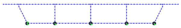
Step 1. Create a 2D frame model. The width of all 2D frames is taken as a unit width (1 ft).
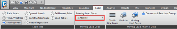
Step 2. Select Transverse for Moving Load Code.
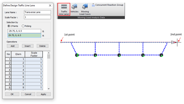
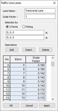
Step 3. Define a Traffic Line Lane on the top slab.
Scale Factors are 1.0 for now.
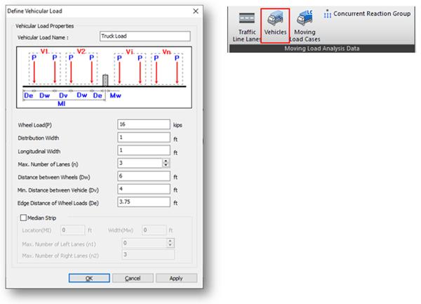
Step 4. Define Vehicles.
Distribution Width represents the width of the slab that may be taken as effective in resisting the bending moment due to wheel loads. These widths are different depending on the position of the slab, i.e. overhang, positive moment region, and negative moment region. We will enter 1.0 here and the distribution width will be taken into account using scale factors from Traffic Line Lane.
Longitudinal Width represents the width of 2D frame elements, which is a unit width.
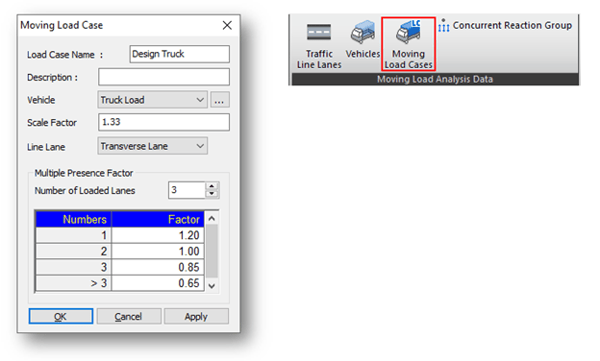
Step 5. Define Moving Load Case.
Scale Factor here can be used to apply for dynamic load allowance. Also, multiple factors should be defined.
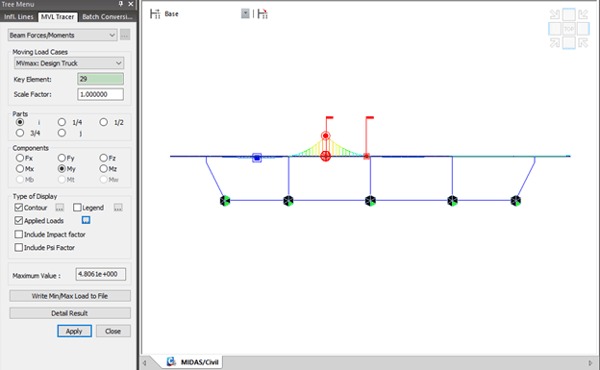
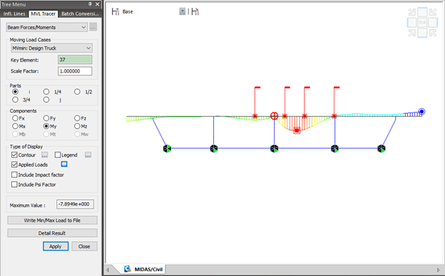
Step 6. Modify Scale Factor from the Traffic Line Lane.
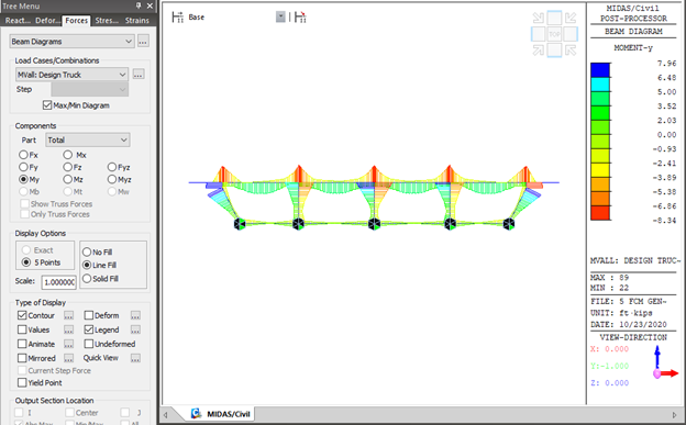
After performing analysis, check the moment diagram due to the moving load case. The scale factor is calculated as 1/W. W represents the distribution width of the wheel load.
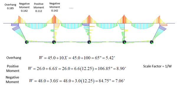
Modify scale factors for each element that corresponds to the overhang, positive moment region, and negative moment region, respectively.
Step 7. Perform analysis and check results.


%20Load/Moving%20Load%20-%20Horizontal%20MovingLive%20Load%20(Centrifugal%20forces)%20345%20240.png)