Get Started midas Civil
 Featured blog of this week

🗂️ Download Now
Please fill out the Download Section below the Comment Section to download the Creep Verification Handout

1. Introduction
A concrete specimen when subjected to load undergoes a response that is both immediate & time-dependent. The time-dependent effect can be majorly induced due to creep & shrinkage. If we talk about the deformation induced for a specimen under sustained loading, then its value increases & can be many times greater than its initial immediate value. Therefore, it becomes essential to consider these long-term effects.
To start with, let’s understand what creep and shrinkage stand for.
Creep: It is the effect due to which concrete undergoes continuous deformation under sustained loading applied for a considerable time.
Shrinkage: It is the drying of concrete and is independent of applied loads. Since shrinkage will cause contraction in concrete, if the contraction is restrained then tensile stress gets developed. This tensile stress can cause the cracking of concrete.
Differential creep & shrinkage: Differential creep & shrinkage exist in the composite structure.
Since the material of the girder and slab can be different, this will induce different time-dependent effects on both. But since both the parts are integrally connected, internal stresses will generate to reduce the differential effect just like eigen stresses develop in the case of temperature.
Even when the same material is used for both girder & deck, the age difference will also cause different time-dependent effects, resulting in differential effects.
To accurately consider the effects of creep & shrinkage, two prerequisites are necessary:
- Reliable data for the creep and shrinkage characteristics of the concrete mix; and
- Analytical and/or numerical procedures for the inclusion of these time effects in the analysis and design of the structure.
2. Characteristics of Creep
As discussed above under sustained stress, creep strain develops gradually with time. But the creep develops rapidly, and later the rate of increase slows appreciably with time as shown in Figure 1.
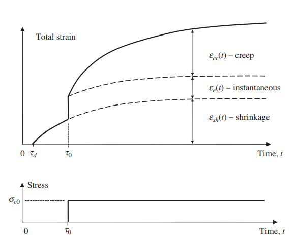
We can infer from the figure that when the time is tending to infinity, creep would be approaching a limiting value. Hence, after several years, the rate of change of creep is quite small. Due to this reason around 50 percent of the final creep develops in the first 2–3 months and about 90 percent develops after 2–3 years.
3. Factors Affecting Creep
Concrete mix: Creep is inversely proportional to the characteristic strength of concrete. So, for a specific stress level, creep would be more in lower-strength concrete.
Aggregate: An increase in aggregate content or the maximum aggregate size reduces creep.
Water-cement ratio: Creep also decreases as the water-to-cement ratio is reduced.
Environment: Creep increases as the relative humidity decreases.
Surface area: Creep is greater in thin members with large surface-area-to-volume ratios, such as slabs. However, the dependence of creep on relative humidity and the size and shape of the specimen decreases as the concrete strength increases.
Ambient temperature: A rise in temperature increases the deformability of the cement paste and accelerates drying, and thus increases creep.
Age of Concrete & loading: Concrete loaded at an early age undergoes creep more than concrete loaded at a later age.
4. Creep Effects
The Creep effects can be categorized in two ways:
- Primary effects: Creep Primary
- Secondary effects: Creep Secondary
The primary effects are independent of the boundary conditions of the structure and can be calculated based on the formulations given in various design codes. While the secondary effects are dependent on the boundary conditions of the structure.
If we talk about the creep primary according to code CEB-FIP 1990, then it is assumed to be linearly related to stress & for constant stress applied at time t0, it can be calculated as:
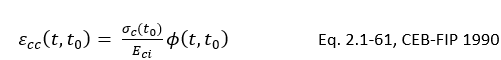
where,
∅(t,t0) is the creep coefficient
Eci is the modulus of elasticity
The creep coefficient can be further calculated as:

where,
∅0 is the notional creep coefficient
βc is the coefficient to describe the development of creep after loading
t is the age of concrete (days) at the moment considered
t0 is the age of concrete at loading (days)
To understand the effects of creep we’ll be taking an example of a simply supported beam.
4.1 Creep Primary
In this example, we’re having a simply supported beam that is loaded with an axial load of 500 kN. Self-weight is not considered for the analysis.
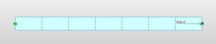 Figure 2. Loading & boundary definition
The maximum axial deformation for this load is 6.847 mm:
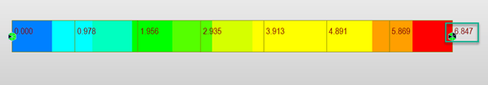 Figure 3. Deformation under axial load
If we check the creep coefficient for a stage duration of 7 days, where the element is activated at the age of 3 days calculated from the software as per code CEB FIP 1990, the value is 0.783
 Figure 4. Creep coefficient function corresponding to 10 days
Using this value, the creep primary deformation can be calculated:
Creep Primary deformation = Creep coefficient x deformation due to sustained stress
= 0.78 x 6.84 =5.3mm
If we check the creep primary deformation for a stage duration of 7 days, where the element is activated at the age of 3 days the maximum deformation is 5.24 mm:
 Figure 5. Deformation under Creep Primary
So, the actual deformation is very close to the deformation obtained as per manual calculation wiz. 5.3mm.
So, in this way creep primary effect is considered. To understand the behavior of creep secondary, we’ll be considering the second example.
In the case of the first example, the structure deformation is not restrained, hence the creep effects will be released, and stress accumulation won’t be dominant. So, in this coming example, we’re considering an integral type of structure. First, it would be simply supported, and at a later stage, the boundary condition would be changed to fixed hence integral action would come into the picture. Once the structure is restrained, the creep effects will not be released, and stress accumulation will occur which can be seen in creep secondary results.
4.2 Creep Secondary
In this coming example, two beams are cast having the support condition as simply supported & loading as shown.
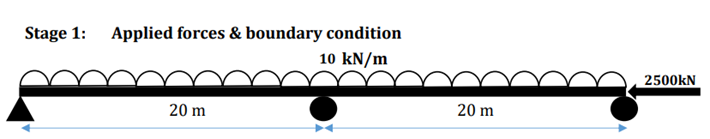 Figure 6. Loading & boundary definition in Stage 1
In this stage, the creep primary effects would be induced according to the member's age & material used. But since the supports are simply supported, the secondary effects will not be dominant here & the values are quite insignificant:
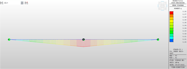 Figure 7. BMD due to creep secondary in Stage 1
But in the second construction stage, the integral action of the beam is simulated, and the end conditions become fixed as shown below:
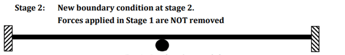 Figure 8. Changed boundary condition in Stage 2
So, here the primary effects would be by the support condition of Stage 1. But since the restrains provided now will not allow for free deformation, secondary effects will be dominant in the structure:
 Figure 9. BMD due to creep secondary in Stage 2
So, from the example above, we can infer that the secondary effects are dependent on the boundary condition provided.
5. Conclusion
From the discussed examples, we can understand why it is important to consider the time-dependent effects. We’ve seen that depending upon the boundary condition, creep secondary effects change for the structure. If the free movement against creep is allowed, then the creep secondary effects won’t be dominant but in case there are restraints provided then these effects become quite dominant. Hence, it is quite important to consider these effects for the structure.
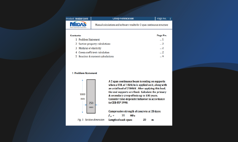
Kindly refer attached document for creep verification.


.png)