Get Started midas Civil
 Featured blog of this week

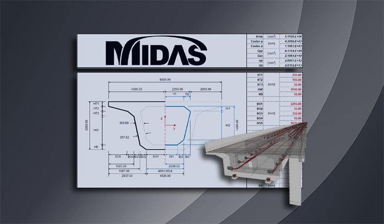
Geometric Properties of Sections
Moment of Inertia (Second Moment of Area)
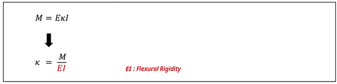
The second moment of area, also referred to as the moment of inertia, is used as a measure to evaluate the flexural rigidity of a section and also to calculate the deflections, flexural stresses, and shear stresses of structures. The formula for calculating the moment of inertia can be derived as, and as a result, the moment-curvature relation can be obtained.
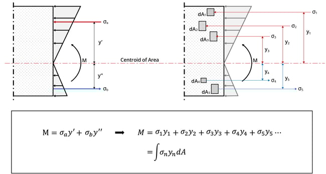
As shown in the figure below, the sum of the moments generated by the normal stresses acting on the section is the same as the moment M. This formula can be re-arranged as an equation for the stress acting on a section divided into n-infinitesimal elements, and the summarized formula is as follows:
If the formula obtained above is substituted with the stress calculation formula of a linear elastic material, it is expressed as follows: The term of the sum of the product of y squared and the cross-sectional area is called the moment of inertia, and is denoted as ‘I’. Since the moment of inertia is the product of the length squared and the cross-sectional area, the unit is expressed as length to the fourth power.
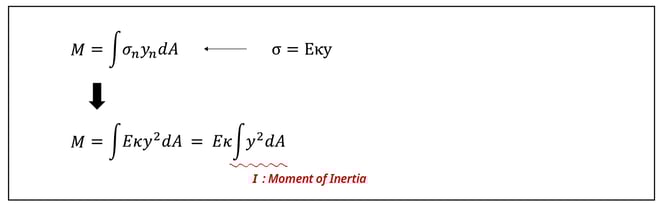
The formula above is summarized for curvature and moment as follows: The curvature κ is proportional to the moment and inversely proportional to the flexural rigidity EI. EI is used as a standard to measure the level at which a structural member can resist bending. Through this formula, it can be known that the elastic modulus and the shape of a member, which are intrinsic physical properties of structural members, are important factors that determine the strength of structures.
When a material with a large modulus of elasticity or a cross-section with a large second moment of area is used, the flexural rigidity increases, and when the flexural rigidity increases, not only the ability to resist bending increases, but also decreases the deflection of the structure because the deflection/deflection angle and second moment of area are inversely proportional.
The formula for calculating the second moment of area derived through the above process can be generalized through the example below. The second moment of area of an arbitrary section with the x-axis as the reference axis is calculated as follows. The distance from the reference axis x to the centroid of area is ‘r’, and the distance from the centroid of area to the n-infinitesimal elements can be subdivided into ‘yn’.
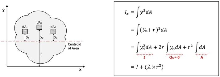
Since the first moment of area ‘QG’, calculated as the integral product of ‘yn’ and the infinitesimal area ‘dA’, is 0, the moment of inertia relative to the x-axis can be calculated as the sum of the moment of inertia ‘I’ and the product of ‘r2’ and cross-sectional area ‘A’. Furthermore, since the cross-sectional area ‘A’ and ‘r2’ are always positive, the moment of inertia becomes the smallest value when the reference axis is the centroid of area.
The moment of inertia is denoted as ‘I’ when the centroid of area is the reference axis, and it is denoted as Ix when the x-axis is the reference axis. It can be seen from the above derivation process that the value of the moment of inertia varies depending on the reference axis. Moving the reference axis from the centroid to the x-axis in order to obtain a generalized expression of the second moment of area according to the reference axis is called the parallel-axis theorem.
Through the rectangular section below, one can check how the second moment of area varies according to the reference axis.
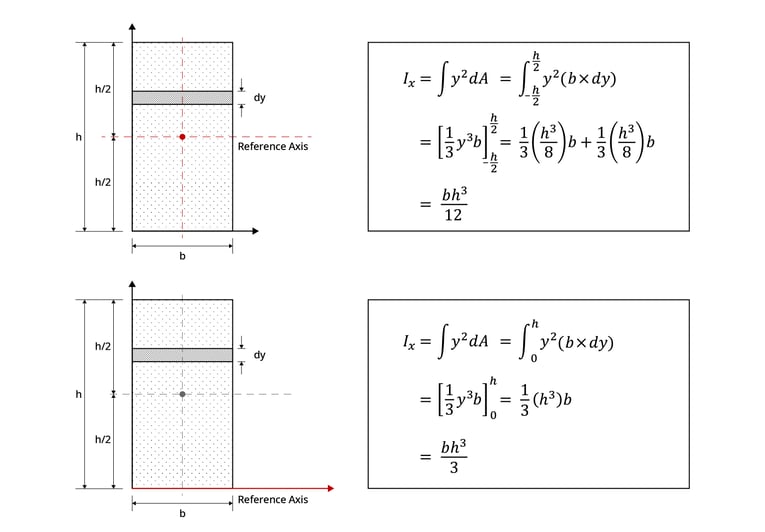 Figure 3: Example on How Moment of Inertia Changes According to the Location of the Reference Axis
It can be seen how the moment of inertia of the rectangular section is different for when the reference axis is located in the centroid of area and when the reference axis is located in the x-axis.
Example: Box-Section Properties
Please look under the DOWNLOAD section below to download "midasBridge Box-Section Properties Calculator" excel template. We have provided an easy-to-use calculator where you can enter the desired Box-section dimensions and get the results for the centroid, first moment of area, and moment of inertia of Box-sections.