 Get Started midas Civil
 Featured blog of this week

This case study covers the following aspects:
1. Introduction to Incremental Launching Method (ILM)
2. Bridge Type
3. Modeling Concepts of temporary works
4. Launching stage analysis using midas Civil
5. In-service stage analysis using midas Civil
6. Design as per AS5100
1. Introduction to Incremental Launching Method (ILM)
Incremental launching is a special construction method of building a bridge to overcome access problems or minimize disruption at ground level. Incremental launched prestressed concrete bridges are built in segments in a casting bed and the finished segments are pushed out of the casting bed to leave space for the construction of subsequent segments. Special knowledge and a high degree of temporary works integration are required in order to successfully design an incremental launch bridge. Most of the superstructure construction activities are carried out at the casting bed area. Bridge barriers, bridge lightings, and drainages can be installed prior to launching.
This technique is generally used for bridges spanning less than 60 meters and require a high degree of technology for both design and construction, and hence demand sophisticated structural analysis and design techniques when compared with other conventional bridges. There are two distinct stages to analyze, the launching stage and the in-service stage. Furthermore, there are also two distinctive groups of pre-stress to accommodate the actions from each of these stages.
2. Bridge Type
|
Structure Type |
Prestressed Box Girder Bridge |
|
Superstructure |
Seven span Continuous Superstructure |
|
Construction Methodology |
Incremental Launching Method |
|
Location of Bridge |
Australia |
3. Modeling Concepts of temporary works
Several aspects of temporary works need to be carefully modeled and designed when using the incremental launching method as a bridge construction methodology. Some of them are explained below.
A. Design of Launch Geometry
Launch geometry design is a key component of the incremental launching bridge design and it is therefore important to evaluate and verify the design of launch geometry.
The launch geometry can either be designed by hand calculations or by Computer-Aided Design (CAD). In CAD, the center and radius of the launch geometry can be quickly obtained by drawing a sphere passing through the three control points along the road alignment. However, to evaluate the launch geometry in CAD, it is a labor-intensive process and the whole process needs to be repeated in order to incorporate the changes in road alignment or abutment location. In contrast, a simple hand calculation method written in spreadsheet format can easily keep up with changes to the road alignment. In most projects, the road alignment is not frozen until the very final design stage. Therefore, the most efficient way to design the launch geometry would be by hand calculation followed by CAD verification once the road alignment is finalized.
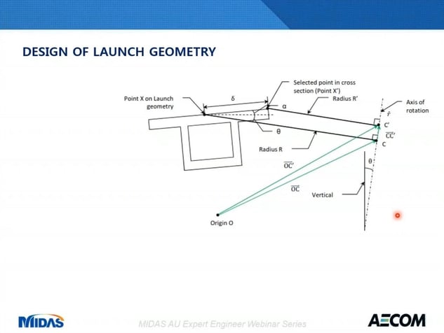
To define a launch geometry, we need to determine the center of launch geometry, the radius of the launch geometry, bearing angle of the vertical radial section, and the inclination of the axis of rotation. These parameters can be calculated by using the coordinates and level of two abutments and the midpoints along with the road geometry.
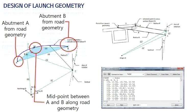
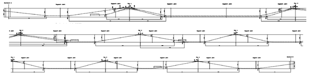
The shape of the bridge deck after launching can be considered as an extrusion of the radial cross-section about the axis of the rotation as shown in figure 2. The trajectory of each point of a cross-section after launching is also a circular arc. Each point of a cross-section has its own radius and center, and shares the same center of the axis of rotation. The coordinates and level of any point in a cross-section along the bridge can be calculated using this method. After that, the design launch geometry will be compared with the design road geometry to see how well the road geometry is approximated. The coordinates, level, cross fall, and bearing angle at supports are the parameters to be compared. If the approximation is not good enough then the designer may need to consider varying the web height or cantilever length to improve the approximation.
Using this method, the coordinates and level of points for the midas Civil model can be calculated. The points are spaced nominally one meter for the launching stage analysis and with additional points to capture segment joints and changing cross-section. The calculated coordinates and level can be easily imported to midas model using the MCT command shell.
B. Temporary Works
There are a number of temporary works that need to be incorporated in a launch bridge design which is shown in figure 3.
The casting bed is placed where the concrete segments are cast and where launching tendons are tensioned. It consists of a couple of spine beams on a rigid foundation and a steel outer form supported on a separate foundation which can be lowered for demoting. During launching, leading segments are cantilevered until they reach the next pier. The launch nose is attached in front of the first segment as shown in the figure to reduce the cantilever bending moment in the concrete segment. Usually, the length of the launching nose is about 70 percent of the maximum launching span. Therefore, the concrete box is dictated by the maximum launching span. The typical span length suitable for launching is between 30 to 60 meters. If the span is too long then the superstructure will become too deep and uneconomical to launch, in this case, temporary tower can be used to reduce the span length during launching. geometry design is a key component of incrementally launching bridge design and it is therefore important to evaluate and verify the design of launch geometry.
Launch jack and braking saddle are installed at the abutment (in front of the casting bed). They utilize the friction to move and stop the superstructure during launching. At the start or end of the launching stage, the available friction is not enough for launching and thereby a separate pulling system is required. For example, a pulling frame is attached to the end of the bridge for this purpose.
Temporary bearing supports the bridge during launching and they are located under the webs and these bearings can be purely temporary or can be converted to permanent bearings afterward. Launchpads are inserted between the bridge superstructure and temporary bearings. There is a sliding surface between the launch pad and a temporary bearing to facilitate launching.
On top of piers and abutments side guides are attached at the top of the pier to provide the lateral restrain during the launching. Table form is to form the bottom face of the top flange and this form is launched together with a segment from the casting bed and this is pulled back to the casting bed after the bottom flange of the next segment is cast. Some contractors may prefer using the precast concrete panel as a permanent form so that table form is no longer required.
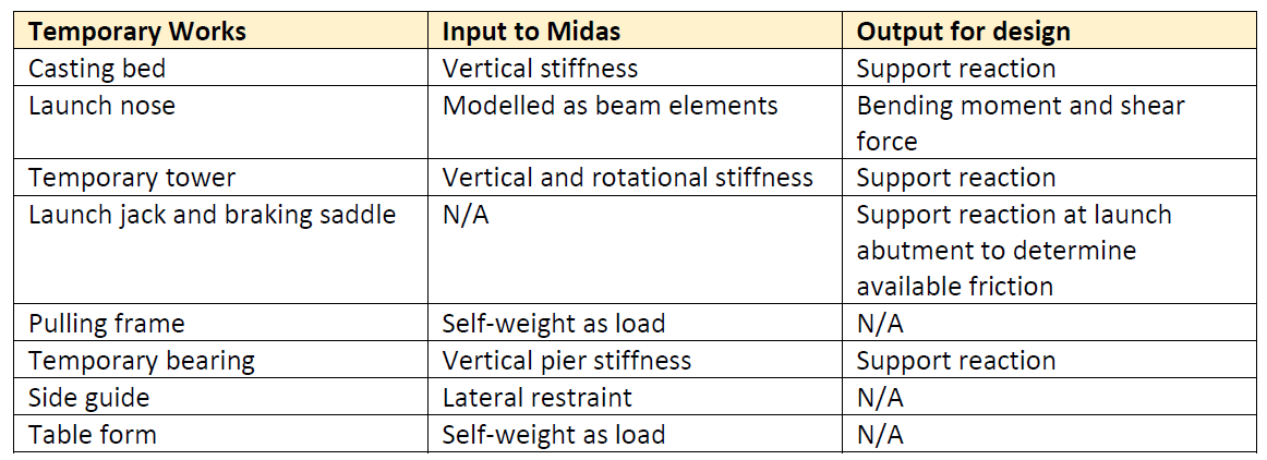
C. Temporary Works in midas Civil
Table 1 summarizes the integration of temporary works to a midas Civil model. In the model, casting bed stiffness is represented by a series of vertical springs. Spring reaction is the load on the casting bed spine beams. Launching nose is modeled in midas as beam elements, typically a launching nose consists of a couple of parallel I beams. In order to not overcomplicate the midas model, these beams are modeled as a single combined beam. After the launching stage analysis, bending moment and shear force envelopes of the launch nose can be obtained from midas model. A temporary tower is modeled as a spring to account for its stiffness. Design actions of this tower are derived from spring reactions. Launch jack and braking saddle are not modeled. Available friction for launching is calculated using the launch abutment reaction.
D. Cross-section of a launched box girder bridge
There are a number of features in the cross-section of launched box girder with many functions.
In most cases, the box section is cast in two pours with a construction joint located at top of the webs as shown in figure 4. Very often the bottom surface of the top flange is formed by a table form which is launched together with the finished segment. It will ride back to the casting bed for the casting of the next segment. For this reason, a continuous path in the cross-section is required at the bottom flange. This means if the local thickening of the bottom flange at several joints is required to accommodate prestressing anchors and such thickening is required at the table form path and this thickening needs to be maintained over the entire length of the bridge.
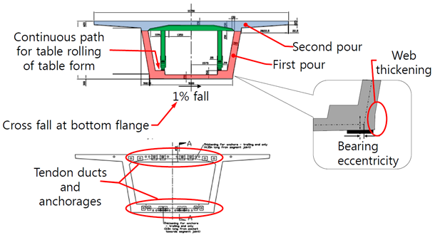
Also, if internal tendons are used for continuity prestress, blisters for prestressing anchorage need to miss the path of the table form. The soffit of the bottom flange is usually provided with a nominal cross fall of 1% to ensure the bridge superstructure always leans against one side during launching.
During launching the bridge is supported by temporary bearing below the webs and the bridge superstructure is supported by temporary bearing below the webs. As the width of temporary bearings is significantly more than web thickness, the center of temporary bearings is always eccentric to the center of the web. Such an eccentricity will create more adverse local bending and shear at the bottom flange. To alleviate such effects may be second at the bottom to reduce bearing eccentricity flanges can be quite congested with tendon ducts and anchorages they need to be wide enough to accommodate all tendons.
In a midas model, the cross-section is input as a PSC session by activating additional cross-section control points, the above-mentioned features can be captured in a Midas model.
4. Launching stage analysis using midas Civil
The purposes of launching stage analysis are:
a. To ensure the stresses in the superstructure during launching comply with the appropriate requirements.
b. To evaluate the load during launching for the design of launching nose, temporary bearings,
temporary pier, launching abutments, and casting bed.
c. To calculate the cumulative shortening of which deck due to pre-stressed creep and shrinkage
during construction.
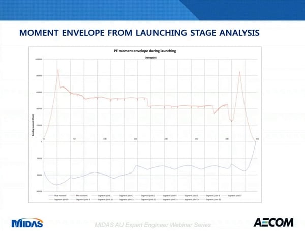
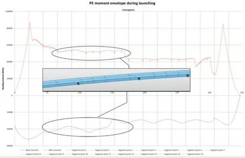
Below figure 5 shows the bending moment envelope of the bridge superstructure from midas analysis.
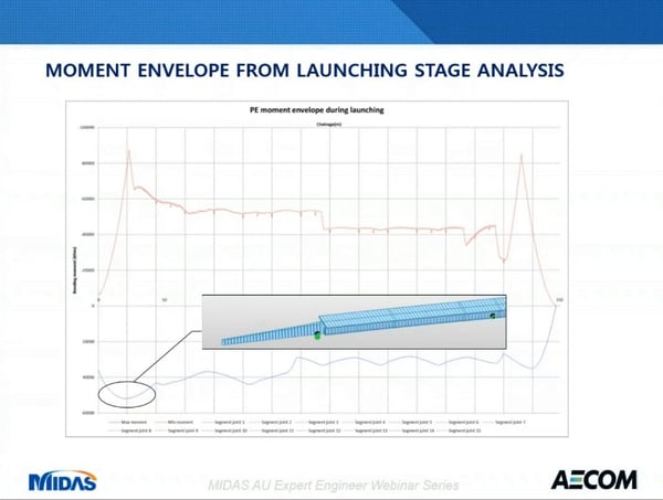
The peak sagging moment of the entire bridge appears at the leading segments. This happens when the leading segments span across the maximum launch span with the leading end of the first segment almost reaches a pier as shown in below figure 6.
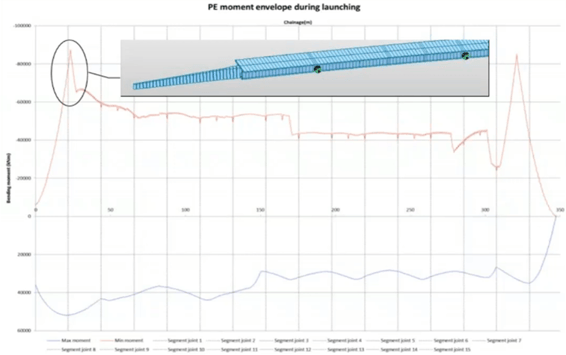
Because the launch nose is light, the cantilever moment of the launch nose offsets only a small proportion of the sagging moment due to concrete weight. The peak hogging moment of the entire bridge also appears at the leading segments. This happens when the launched nose cantilevers at the maximum span just before the tip of the launched nose reaching the next pier as shown in below figure 7.
The sagging and hogging moment of intermediate spans is uniform. This is because each cross-section alternates between the midspan section and the support section. Figure 8 shows two distinctive magnitudes of the moment with the magnitude of the second part being lower. This means that the pier of the second half of this bridge is more closely spaced.
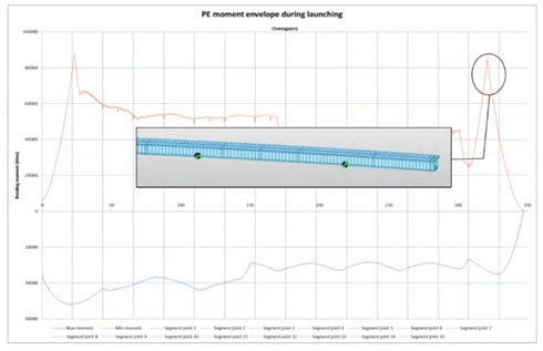
Another peak as shown in below figure 9 towards the trailing end of the bridge, this happens when the trailing end of the bridge leaves the casting bed and becomes a cantilever. There is one potential critical stage hidden inside this envelope. It happens when a segment is launched with some of the tendons in the flange stressed. Typically, tendons in flanges are two or three segments long. The tendons are staggered so that only half or a third of them are stressed at each launching stage.
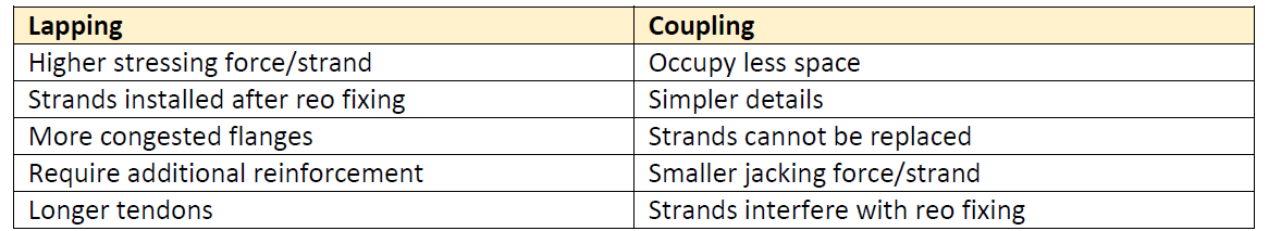
Arrangements of launching pre-stress can be determined according to the total action during launching. This plan (figure 10) shows the launching pre-stress arrangement of top and bottom flanges in the first two segments. Tendons of the launching can be lapped or coupled at the segment joints.
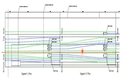
Tendons in this arrangement are lapped at segment joints. The blue tendons are the tendon stressed after casting of the first segment and the green tendons are the tendons that are stressed after casting of the second segment. For the coupling option, tendons are coupled at seven joints using proprietary couplers. Comparison of lapping versus coupling is indicated in table 2.
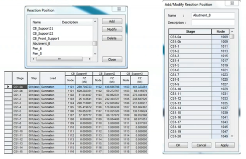
Furthermore, midas has a very useful feature called reaction position table since launching stage analysis is simulated by moving support networks the same pier is represented by different nodes at different stages reaction position table is to correlate the node number and stages with each pier or apartment to facilitate the output of support reactions.
During launching concrete segments become shorter due to elastic shortening at the transfer of pre-stress and subsequent creep and shrinkage. If uncorrected, then the diaphragm of the superstructure will not align with piers and abutments, as a result, the cumulative shortening of segments obtained from launch stage analysis needs to be compensated during casting. Such information can be easily obtained from Midas.
5. In-service stage analysis using midas Civil
After the launching stage analysis, In-service stage analysis is carried out to evaluate the transient effect as well as the load during bearing replacement. SM 1600 live loads are predefined in Midas for influence line analysis. If the box girder section is defined as a PSC section, then the temperature profile for differential temperature can be defined directly as beam section temperature loading.
To design a pre-stressed concrete bridge, we typically need to know the moment envelope shear envelope and torsion envelope and the coexisting effects. Design envelopes and coexisting actions can be conveniently obtained from Midas.
Continuity pre-stress is provided according to actions due to transient effects as shown in figure 12. Continuity prestress can be provided as internal tendons within web or external tendons inside the box. Since there are no tendon ducts inside the web, external tendons can simplify segment construction and they are easy to install.
6. Design as per AS5100
Below checks need to be performed as per AS5100:
1. SLS Bending Stress at Tendon Level for Exposure B2, C1, C2, U (AS5100.5 Clause 8.6.2.3)
2. SLS Stress Increment Check (AS5100.5 Clause 8.6.2.1(b))
3. ULS Bending Moment Capacity (AS5100.5 Clause 8.1)
4. ULS Shear and Torsion Capacity (AS5100.5 Clause 8.2)
5. Transverse Analysis
6. ULS Longitudinal Shear at CJ and Web/Flange Interface (AS5100.5 Clause 8.4)
Furthermore, AS5100 part to clause 7.11 does not allow sag deflection under permanent loads.
Vertical camber cannot be incorporated during segment casting. The only way to reduce sag deflection is by continuity pre-stress. However, it would be uneconomical to eliminate sag deflection solely by continuity pre-stress, especially for longer spans.
Therefore, the effect of net sag deflections should be assessed with respect to:
A. Visual impact
B. Required clearance underneath the bridge C. Bridge deck drainageD. Loading (e.g. extra surfacing thickness)
Watch the full webinar video


/(BI)%20What%20is%20the%20Influence%20Line%20and%20Surface%20Analysis%20on%20bridges/Influence%20Line%20%26%20Surface%20Analysis%20on%20Bridges%20345%20240.png)