Get Started midas Civil
 Featured blog of this week

This webinar shows a case study about the steel composite ladder deck girder bridge. The webinar will highlight major factors to consider in the design of this type of bridge, such as shear lag and buckling effects. It will provide recommendations on the suitability and use of different model types. Since many ladder deck bridges are constructed using the push launch method, special considerations for the construction sequence will be discussed.
In this session, Martin Bosak from Barry Transportation shares the presentation regarding modeling approaches including the geometry, model properties, loads, and construction stage analysis with the steel ladder deck bridge.
This case study highlights:
1. Purpose of Different Model Types for Steel
More than one type of structural model may be necessary for the steel bridge design. The speaker will talk about the purpose of different modeling methods and how those models can be created.
2. Deck Slab Considerations
The presentation will discuss whether and how to include effects of shear lag in the concrete deck as well as cracked concrete over bridge supports.
3. Special Considerations for Push Launch Construction
The stability of the bare steel structure during construction may be a deciding factor in the design. The webinar will provide guidance in this important aspect of the bridge design.
1. Purpose of Different Model Types for Steel Bridge Design
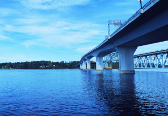
The model for the case study is a steel composite ladder deck girder bridge. The bridge has twin steel girders and a concrete deck, and it is constructed by the Push Launch Method. Here you can find some information regarding the bridge.
/Steel%20ladder%20Deck%20Bridge%20Design/New%20Images%20Steel%20Ladder%20Deck%20Bridge%20Design/%EC%9D%B4%EB%AF%B8%EC%A7%80%201.png?width=1314&name=%EC%9D%B4%EB%AF%B8%EC%A7%80%201.png)
/Steel%20ladder%20Deck%20Bridge%20Design/New%20Images%20Steel%20Ladder%20Deck%20Bridge%20Design/%EC%A0%9C%EB%AA%A9%20%EC%97%86%EC%9D%8C-1.png?width=734&name=%EC%A0%9C%EB%AA%A9%20%EC%97%86%EC%9D%8C-1.png)
Now, let's look at various modeling approaches. When we create and analyze a model, we have a number of options as a designer. Here are some approaches for modeling.
Approach no.1. 3D Frame(Grillage) Model
Purpose
- Construction stage analysis (Launch, deck construction)
- Global static analysis
- Support reactions (bearing design), deformations, member design and verification (main girder)
/Steel%20ladder%20Deck%20Bridge%20Design/New%20Images%20Steel%20Ladder%20Deck%20Bridge%20Design/%EC%9D%B4%EB%AF%B8%EC%A7%80%207.png?width=733&name=%EC%9D%B4%EB%AF%B8%EC%A7%80%207.png)
Approach no.2: Mixed Type Model
(Deck and main girder web as plates, crossbeams and/or girder flanges as line beams)
Purpose
- Stability verification during construction
- Transverse deck analysis and design
/Steel%20ladder%20Deck%20Bridge%20Design/New%20Images%20Steel%20Ladder%20Deck%20Bridge%20Design/%EC%9D%B4%EB%AF%B8%EC%A7%80%208.png?width=731&name=%EC%9D%B4%EB%AF%B8%EC%A7%80%208.png)
Approach no.3: Full Plate Model
(All elements modeled as plates, including crossbeams and stiffeners)
Purpose
- Detailed analysis of crossbeams
- Local verification (Stiffener buckling, local web buckling, stress concentrations)
/Steel%20ladder%20Deck%20Bridge%20Design/New%20Images%20Steel%20Ladder%20Deck%20Bridge%20Design/%EC%9D%B4%EB%AF%B8%EC%A7%80%209.png?width=737&name=%EC%9D%B4%EB%AF%B8%EC%A7%80%209.png)
/Steel%20ladder%20Deck%20Bridge%20Design/New%20Images%20Steel%20Ladder%20Deck%20Bridge%20Design/%EC%9D%B4%EB%AF%B8%EC%A7%80%2010.png?width=734&name=%EC%9D%B4%EB%AF%B8%EC%A7%80%2010.png)
2. Deck Slab Considerations
If you decide to use the grillage model for your model, you have to consider some factors. In midas Civil, you can model each part using Composite section type and Steel section type, and you can use dummy elements to complete the grillage model.
/Steel%20ladder%20Deck%20Bridge%20Design/New%20Images%20Steel%20Ladder%20Deck%20Bridge%20Design/%EC%9D%B4%EB%AF%B8%EC%A7%80%2011.png?width=734&name=%EC%9D%B4%EB%AF%B8%EC%A7%80%2011.png)
It is necessary to take into account the effects of shear lag in the concrete deck when you have the grillage model. There are provisions in Eurocode 4 on how to calculate participating width of a concrete slab. The steel composite ladder deck bridge has just 2 main girders. The distance of the 2 girders is not short so we need to calculate participating width called the effective width.
/Steel%20ladder%20Deck%20Bridge%20Design/New%20Images%20Steel%20Ladder%20Deck%20Bridge%20Design/Deck%20Slab%20Considerations.png?width=734&name=Deck%20Slab%20Considerations.png)
Next, we need to check the effect of cracked concrete. We know that the tensile stresses or large hogging moments at the internal support make cracks at the concrete deck. It makes the stiffness of concrete to be decreased. In order to consider the effect, midas Civil provides the Section Manager to adjust the stiffness as the scale.
/Steel%20ladder%20Deck%20Bridge%20Design/New%20Images%20Steel%20Ladder%20Deck%20Bridge%20Design/%EC%9D%B4%EB%AF%B8%EC%A7%80%2013.png?width=733&name=%EC%9D%B4%EB%AF%B8%EC%A7%80%2013.png)
If you decide to use plate elements for your model, you don't need to deal with the effective width of the slab - the shear lag effect is included implicitly within FEM model. The effect of a cracked concrete slab over supports may be modeled by material properties of concrete (Reduced the elasticity modulus value, using the orthotropic material), and it is necessary to pay attention to proper mesh size and element shapes.
/Steel%20ladder%20Deck%20Bridge%20Design/New%20Images%20Steel%20Ladder%20Deck%20Bridge%20Design/%EC%9D%B4%EB%AF%B8%EC%A7%80%2014.png?width=790&name=%EC%9D%B4%EB%AF%B8%EC%A7%80%2014.png)
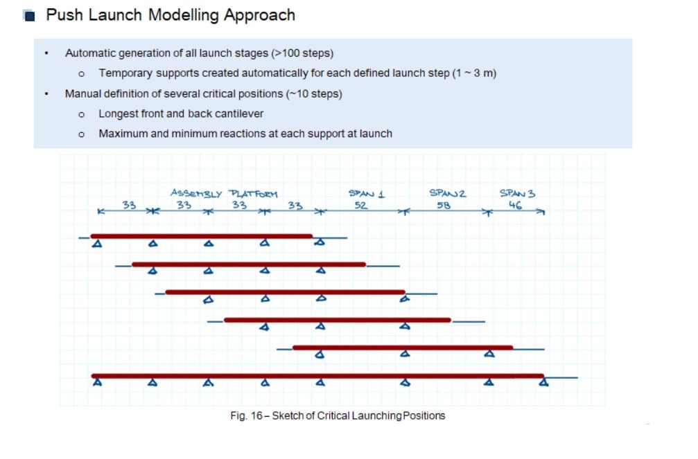
3. Special Considerations for Push Launch Construction
The steel ladder deck girder was constructed by using the push launch method. Here are the considerations for the push launch method.
/Steel%20ladder%20Deck%20Bridge%20Design/New%20Images%20Steel%20Ladder%20Deck%20Bridge%20Design/%EC%9D%B4%EB%AF%B8%EC%A7%80%2017.png?width=734&name=%EC%9D%B4%EB%AF%B8%EC%A7%80%2017.png)
We have 2 options for the modeling approach of the push launch method. Depending on the designer's decision, automatic generation method or manual definition of several critical positions.
After the push launch work, we have the deck construction. We have 2 options for the deck construction to consider this work in SW.
/Steel%20ladder%20Deck%20Bridge%20Design/New%20Images%20Steel%20Ladder%20Deck%20Bridge%20Design/%EC%9D%B4%EB%AF%B8%EC%A7%80%2018.png?width=734&name=%EC%9D%B4%EB%AF%B8%EC%A7%80%2018.png)
/Steel%20ladder%20Deck%20Bridge%20Design/New%20Images%20Steel%20Ladder%20Deck%20Bridge%20Design/Deck%20Construction%20-%20Factors%20to%20Consider.png?width=734&name=Deck%20Construction%20-%20Factors%20to%20Consider.png)
We looked into considerations for the general design and modeling of a steel ladder deci\k bridge. In the next blog content, we will have time to check detailed modeling works with midas Civil.
Watch the full webinar video