 Get Started midas Civil
 Featured blog of this week

Please fill out the Download Section (Click here) below the Comment Section to download the Culvert Rigid End Distance Excel Sheet
Table of Contents
*Click the content to move to the section
1. Why Should We Consider Rigid End?
2. Design Criteria for Rigid End
3. Differing Moments Based on Rigid End Consideration with midas Civil
4. Conclusion
1. Why Should We Consider Rigid End?
Typically, rahmen, culverts, and steel structures are modeled by frames or Beams Member. These models typically result in overlapping of sections where two components meet, such as where columns and beams or chord members and braces meet, when modeled using CTC (Center to Center).
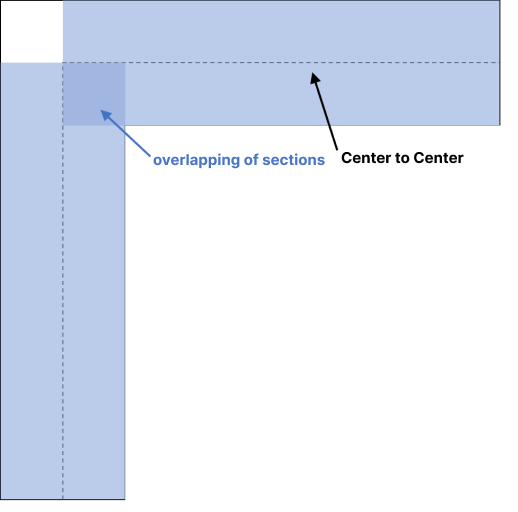
Rigid End refers to a section where an increase in deformation due to overlapping of two cross sections is prevented by increasing the rigidity of the end or by using an option that suppresses the occurrence of a moment."
2. Design Criteria for Rigid End
Consideration of Rigid End can be at the discretion of the engineer. In the design criteria for road bridges, howeber, the impact of Rigid End is considered when calculating sectional forces, and analysis is performed accordingly.
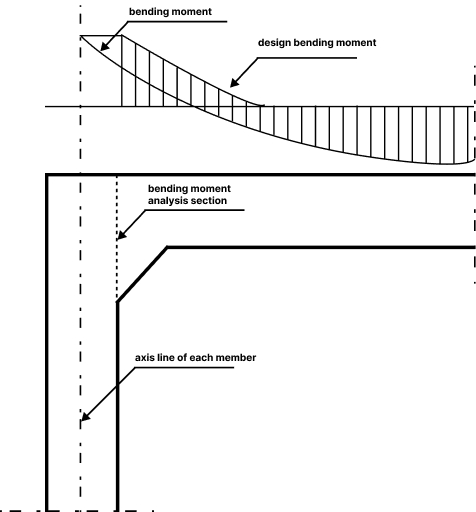
According to KDS 44 90 00, the design criteria for road culverts, "In structural analysis, the effects of haunches on flexural rigidity and changes in member curvature because they had minimal impact." In this case, the bending moment acting on the end points of the component is shown in the diagram below. Calculating Rigid End according to the method suggested in the design criteria for road bridges is required.
The calculation method for Rigid End distance suggested in the the design criteria for road bridges specification(2008) is as follows:
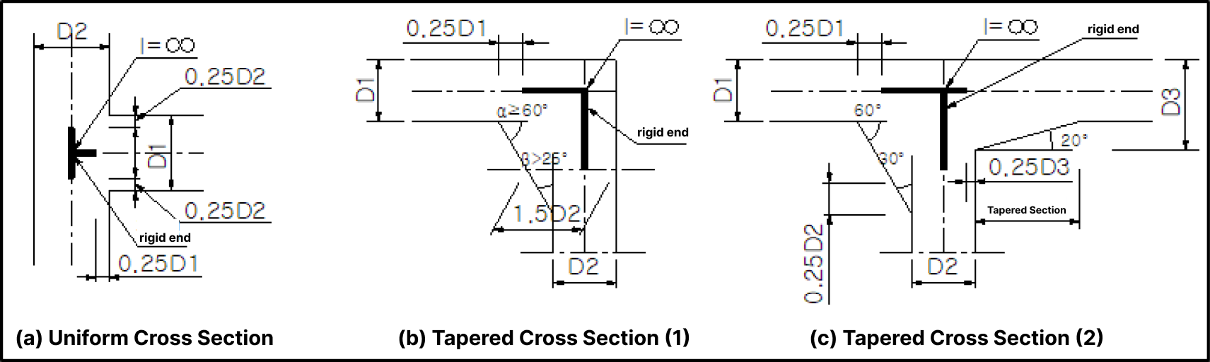
(A) For Uniform Cross Section : When the component ends connect to a different component, calculate the Rigid End distance from a point inside the component thickness, 1/4 of the distance from the component edge to the end point.
(B) For Tapered Cross Section (1): When the component has an inclined haunch with an angle of 25 degrees or more and less than 60 degrees with respect to the axis, calculate the Rigid End distance from a point on the component thickness where it is 1.5 times thicker than at the end point to the end point.
(C) For Tapered Cross Section (2): When the haunch angle is 60 degrees or more, calculate the Rigid End distance from a point inside the component thickness, 1/4 of the distance from the hunch vertex to the end point.
Let's take a look at how to calculate the Rigid End distance for two cases through examples.

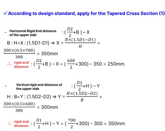
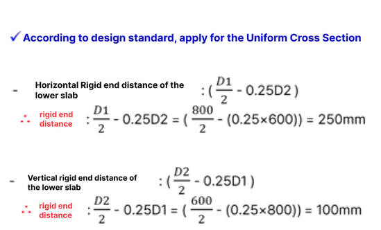
The calculation of rigid end can be easily calculated using the method described above.
3. Differing Moments Based on Rigid End Consideration with midas Civil
It is generally known that a more economical section can be designed when considering a rigid end.
If a rigid end is not taken into account, there is a high possibility of significant moment generation, which can be addressed through conservative design. However, this approach can lead to designs that are unnecessarily over-engineered, resulting in larger structural elements than necessary.
To compare the moment before and after considering rigid end, we used midas Civil to see how much difference there is.
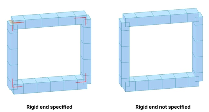
The figure below shows an approximate cross section of a structure used for comparison, along with a model that considers rigid end and a model that does not.
In midas Civil, the consideration of rigid end is modeled using the Beam End Offsets feature.
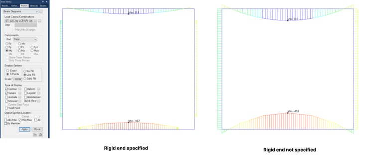
The calculated moments using the two models are shown in the figure below.
Although the difference is not significant, it can be seen that the moment decreases by 5.63% when comparing the model that considers rigid end and the model that does not.
As expected, when considering rigid end, it is possible to exclude unnecessary cross-sectional forces and design a more economical section that reflects the actual shape of the structure.
4. Conclusion
In the case of models using frames or beams, rigid end should be considered to take into account changes in stiffness at overlapping parts.
The calculation of rigid end distance can be done according to the [KDS 24 14 00] Bridge Structural Design, and if you use the function of midas Civil when creating a model, you can automatically consider it.
The consideration of rigid end does not significantly affect the safety of the structure. However, an engineer who does not ignore even small parts can design a safer and more economical structure, so please check the contents at least once.
At the bottom of the content, an Excel calculation sheet that makes it easy to calculate rigid end has been prepared so that you can apply the blog content directly. The rigid end distance for cases of equal section and variable section according to the design standards for concrete bridges (ultimate strength design method) KDS 24 14 20 can be calculated.
👉To see related contents, please click on the tags under the Topic section below.


/Static%20Analysis%20of%20Cable-Stayed%20Bridges/Static%20Analysis%20of%20Cable-Stayed%20Bridges%20345%20240.png)