Get Started midas Civil
 Featured blog of this week

A. Introduction
I'd like to share my old experience with the Tendon Profile.
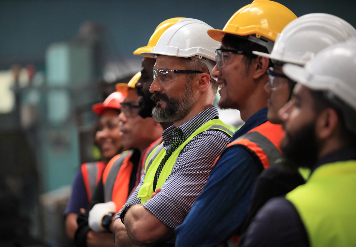
I was involved in a bridge project in Kuwait about 10 years ago. There were design teams from various countries working together, and my team was responsible for the design of the ramp area.
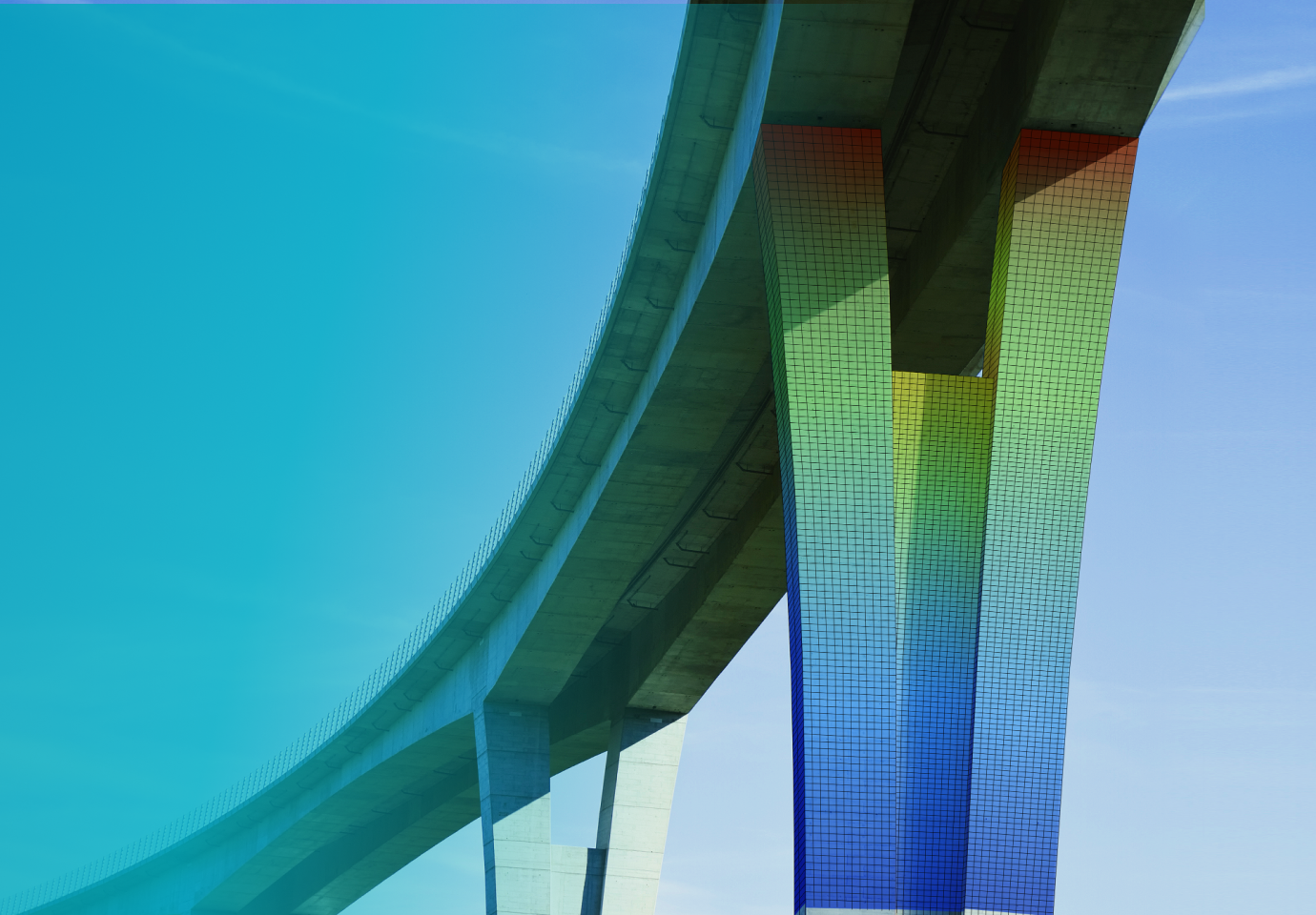
As we all know, ramp bridges have a small radius, so steel bridges are generally preferred.
However, despite the minimum radius being 55m, the PSC box girder section was suggested to our team for the preliminary design.
This is where the challenges start!
The first major challenge that needed to be addressed for this project was creating a structural analysis model using MIDAS CIVIL software.
But at that time, my senior engineers told me about well-known issues with MIDAS CIVIL.
“Element Type should not be used, and Straight Type should be used for the curved bridge."
In this content, we will discuss the above issue in detail.
Why is it recommended to use Straight Type instead of Element Type when designing curved bridges?
And how was the Straight Type applied in practical use?
So let's get started.
B. Tendon Profile in MIDAS CIVIL
B.1 The Types of Tendon Profile
First, let's check what options are available in the tendon profile dialogue box of MIDAS CIVIL.
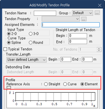
MIDAS CIVIL - Add/Modify Tendon Profile
MIDAS CIVIL provides three options for tendon profiles.
Let’s check the MIDAS CIVIL reference manual to understand each function.
- Straight: the x-direction (the reference line from which tendon coordinates are defined) of TCS for tendon placement is considered a straight line.
- Curved: the x-direction (the reference line from which tendon coordinates are defined) of TCS for tendon placement is considered a straight lie.
- Element: Tendon location is converted into Element Coordinate System and applied.
B.2 Comparison of results based on the Tendon Profile
To understand the differences among the three options, let's introduce tendon forces in a straight member and a curved member (a series of straight segments) and observe the differences in their results
Example 1: The configuration of the straight member is shown in the figure below. Let's compare the section forces due to tendon forces.
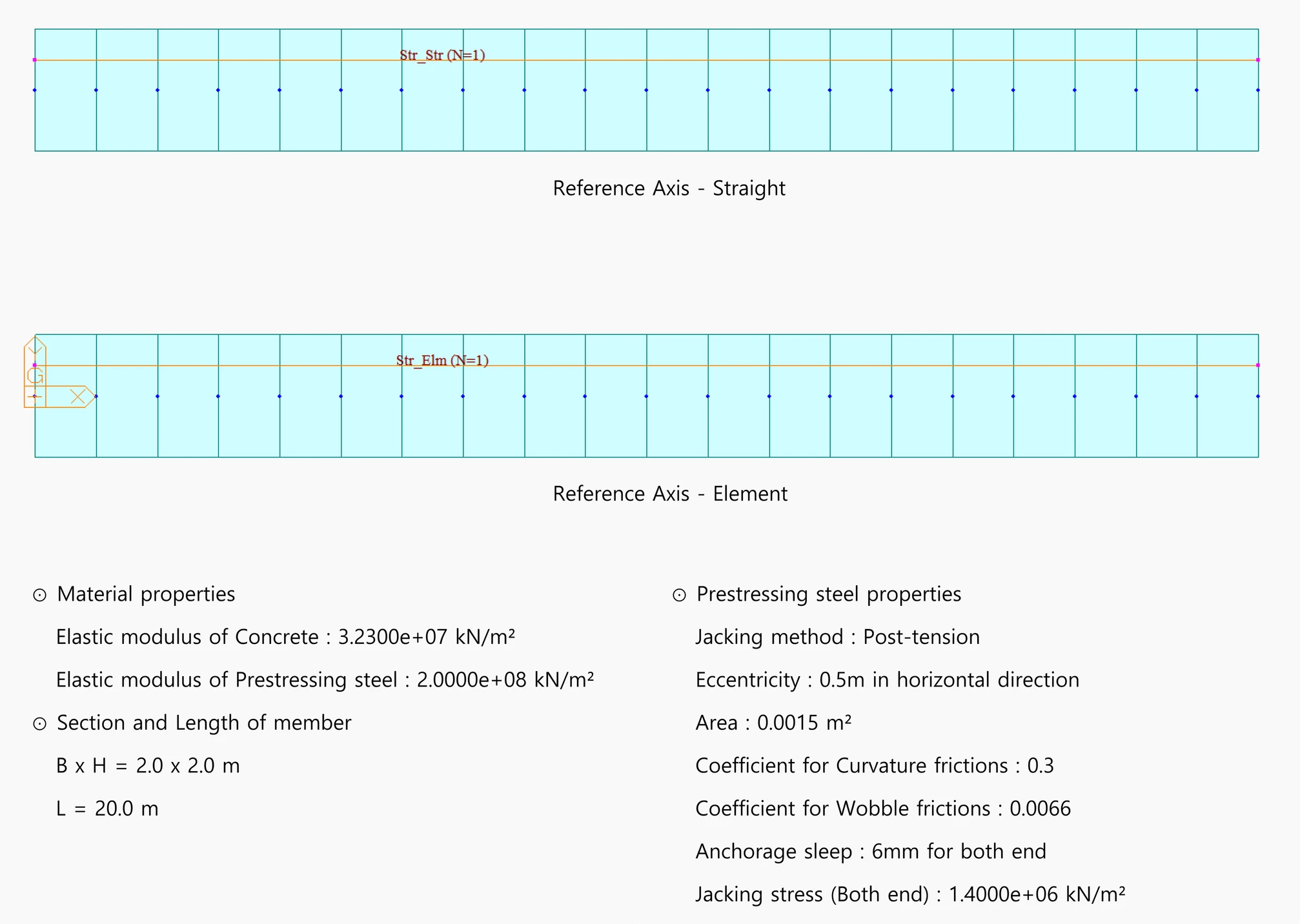
Example 1: Configuration of the straight member.
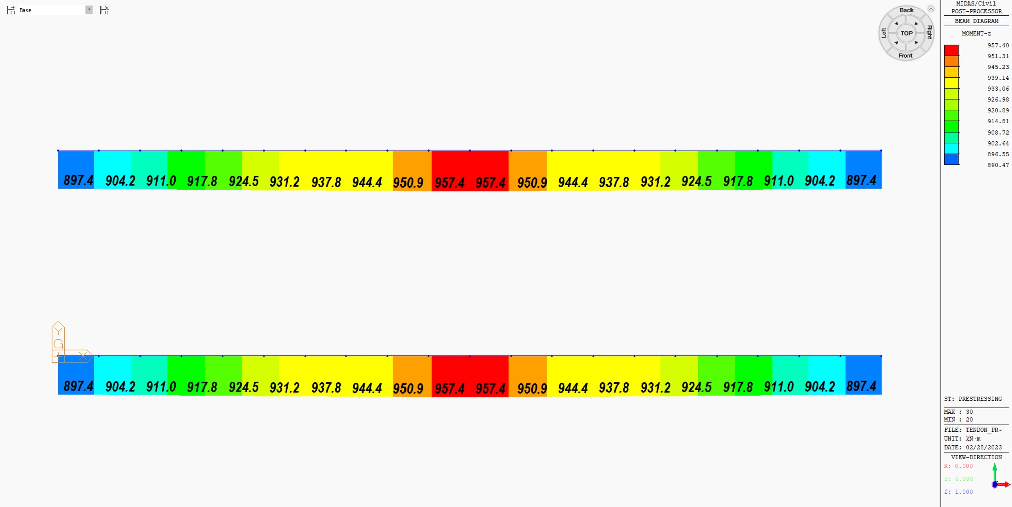
Example 1: Transverse Moment Mz due to Tendon Force.
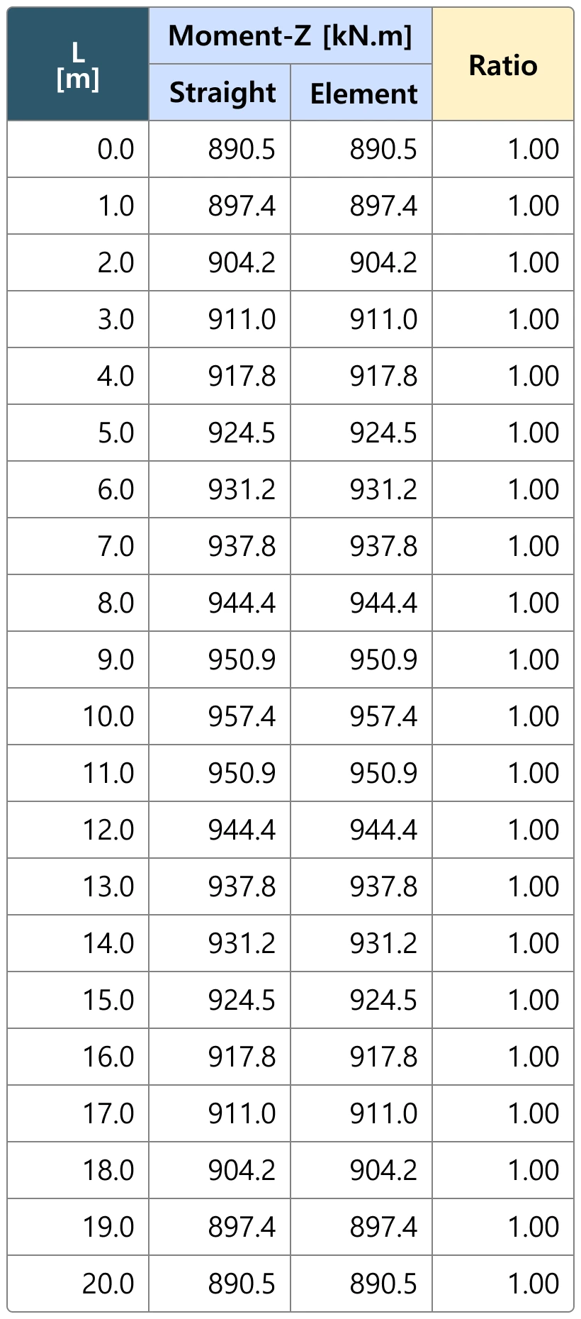
Example 1: Transverse Moment Mz due to Tendon Force.
The results of a straight member are the same regardless of the reference axis.
Example Ⅱ: The configuration of the curved member is shown in the figure below. Let's compare the section forces due to tendon forces.
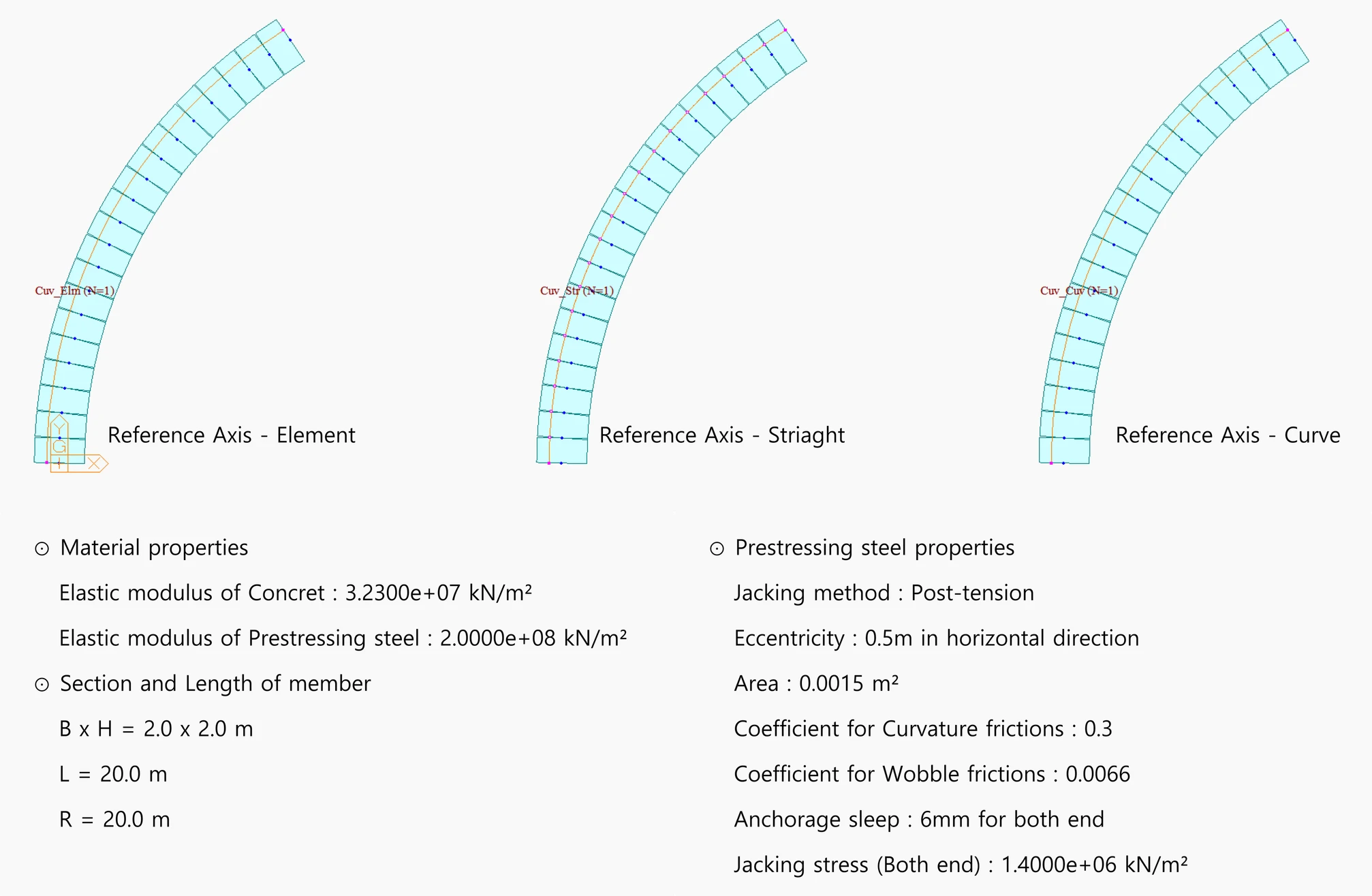
Example 2-Configuration of a Curved Member
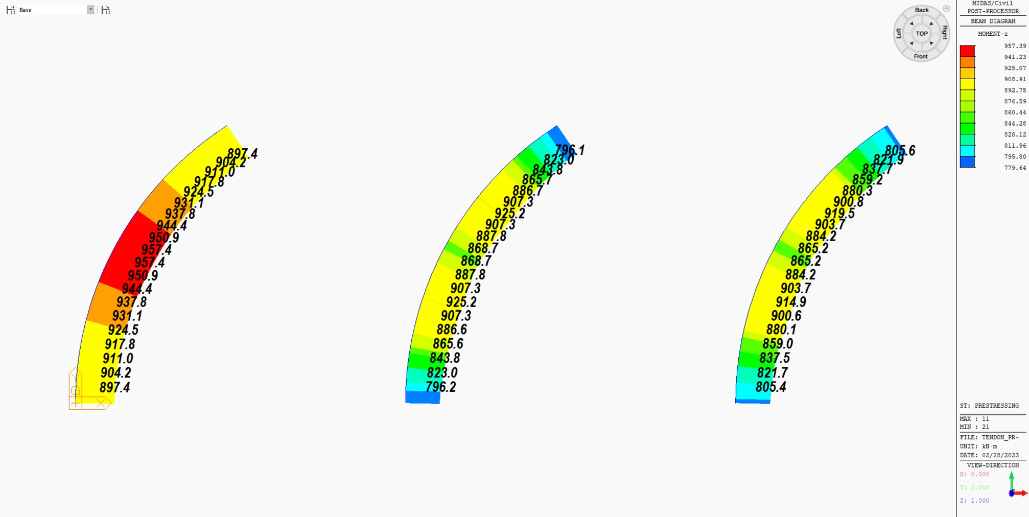
Example 2: Transverse Moment Mz due to Tendon Force
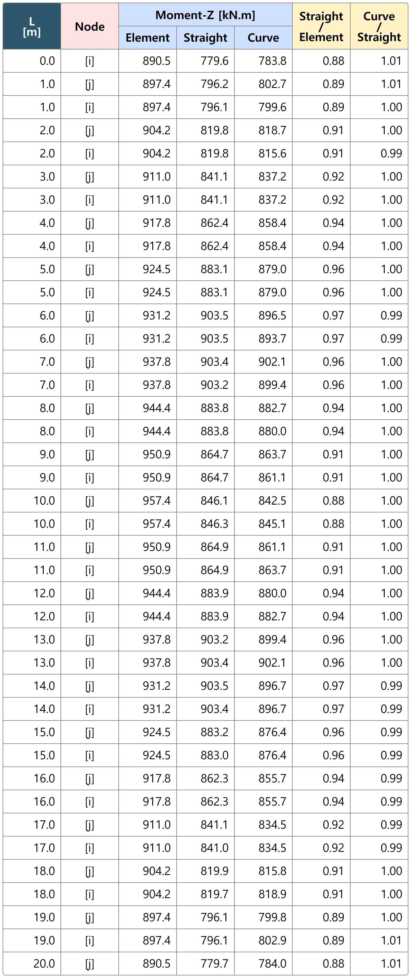
Example 2: Transverse Moment Mz due to Tendon Force
For the curved member, both straight and curved configurations show similar results. However, the elements exhibit a difference of approximately 3-10% in sectional forces
The discrepancy in transverse moment Mz implies that the tension loss may have caused it.
B.3 Tension loss
before moving further to check the difference in results observed in Example 2, let’s briefly discuss the tension loss.
The prestressing force does not remain constant over time but it reduces over the service life of the structure due to various factors that cause prestress loss.
The various types of prestress losses are as follows:
Ⅰ. Instantaneous Loss
Ⅰ-ⅰ Elastic Shortening
Tension loss occurs when the length of the member decreases due to the applied prestressing force, which causes a loss of tension force in the tendon.
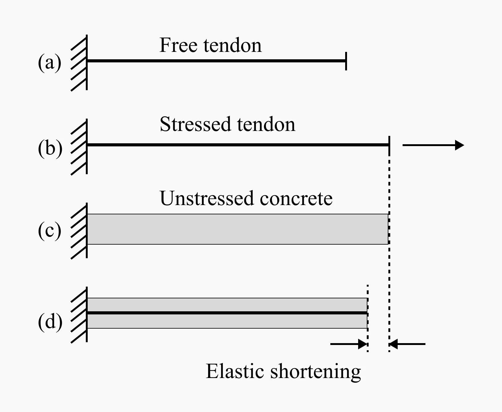
Schematic representation of elastic shortening (a) Free tendon. (b) Stressed tendon. (c) Unstressed concrete. (d) Shortening at transfer
For post-tensioning, no tension loss occurs when only one tendon is tensioned. This is because the member acts as a counterbalance, preventing any loss of tension.
However, when multiple tendons are sequentially tensioned, tension loss occurs due to the elastic shortening of concrete.
In general, the first tendon that is stressed does not experience tension loss due to elastic shortening. However, tension loss occurs during the stressing process of subsequent tendons. As a result, the first tendon stressed typically experiences the greatest loss, while the last tendon stressed does not experience any loss due to elastic shortening
In pre-tensioning, immediate loss occurs during the process of releasing the tendon from the anchorage, which results in an instantaneous elastic shortening of the tendon due to its elongation during pre-stressing.
Ⅰ-ⅱ Friction
The friction loss caused by the friction between the strand and the duct (belt friction) occurs only in the case of post-tension.
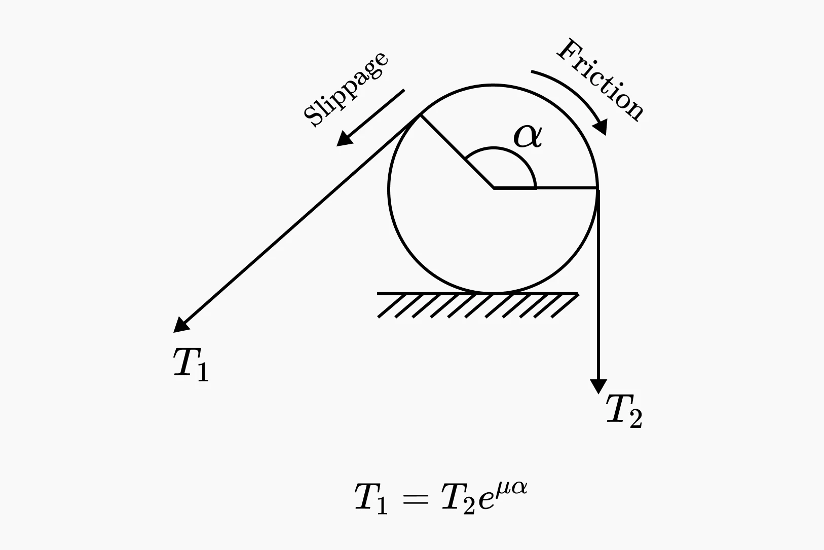
Belt friction
Curvature friction
- Occurs when ducts are arranged in curvature.
- Frictional losses due to belt friction occur when the steel tendons come into contact with the inner curvature of the ducts during prestressing.
- The larger the change (angle) in the ends of the prestressing tendons, the greater the frictional losses are.
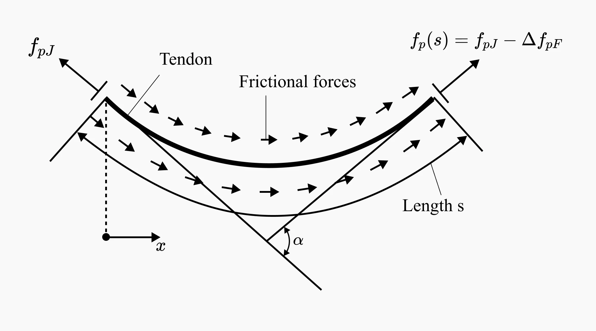
Curved prestressing tendon
Wobble friction
- Even though ducts may be theoretically arranged in a straight line, in reality, ducts cannot be perfectly straight.
- For example, even if ducts are arranged in a straight line, support points are necessary during installation to prevent sagging caused by the weight of the ducts between the support points.
- Therefore, the loss due to wobble friction increases as the length of the duct increases.
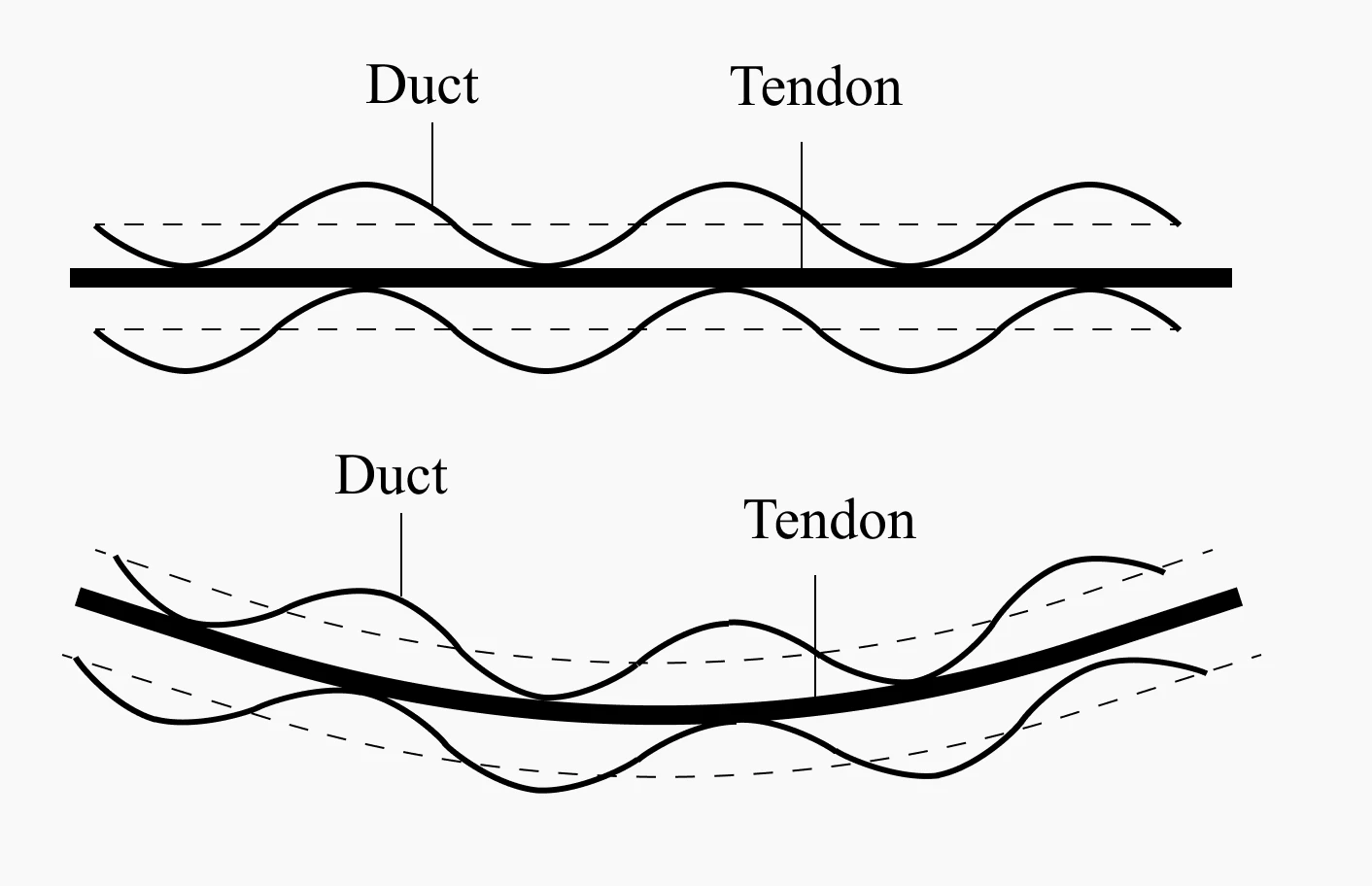 Wobble effects
Ⅰ-ⅲ Anchorage Slip
Most post-tensioning systems use wedge-type anchorage devices, during tensioning, the wedges are pushed into the anchorage, causing the strands to be compressed together.
This refers to the loss that occurs due to the movement of the anchorage device over a distance.
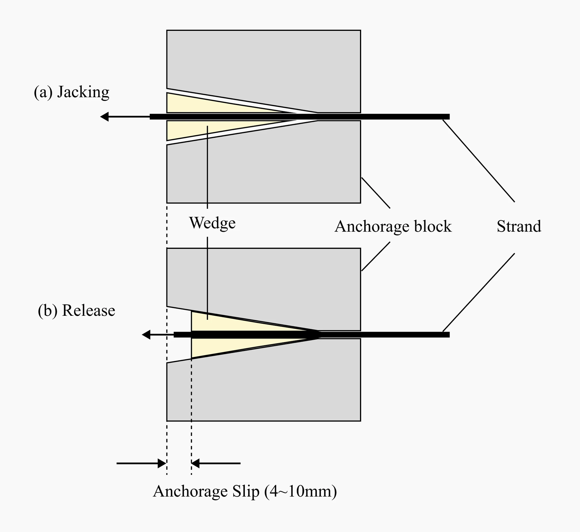
Anchorage Slip
Ⅱ. Time-dependent Loss
Time-dependent losses occur due to the characteristics of materials, so the calculation methods for these losses vary depending on the design criteria.
Therefore, it is important to carefully examine and apply the design criteria that must be applied to the project
Ⅱ-ⅰ Relaxation
Relaxation refers to the loss of tension in a prestressing material over time.
Common reasons for relaxation include internal defects in the prestressing material, thermal expansion, and plastic deformation.