 Get Started midas Civil
 Featured blog of this week

Rail Structure Interaction Wizard in midas Civil
The key feature of Rail Structure Interaction (RSI) Wizard is to generate model files considering various parameters automatically for checking stress and displacement results. The wizard provides two modeling approaches, a simplified separate analysis method, a complete analysis method, and it considers boundary changes such as the changed resistance of ballast depending on trainload. After modeling, RSI Wizard generates a summary report to help a user to check results at once.
Rail-Track Analysis Model
Layout Tab
Let’s have a look at detailed descriptions of the RSI Wizard. When the user turns on the RSI Wizard, the wizard presents the Bridge Data tab. The Bridge Data tab is used to define the geometry of the model such as the number of a span of the bridge, the length of a span, material type of a span, the length of embankment, the support type of a span, and the section of rail.
Some options have the Advanced option. The user can assign different conditions for each span with the Advanced option.
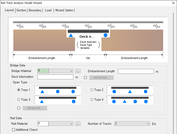 Figure 1. Layout tab of the RSI Wizard
Under the Rail Data, the user can see the Additional Check option. This option is used to set additional conditions for the rail. The first one is the Zero Longitudinal Resistance (ZLR) option. This option considers the zero longitudinal restraint system of the rail but doesn’t provide longitudinal resistance to the rail. To set this option, input the start position and end position in which the ZLR is located. The below figure shows an example of ZLR zone.
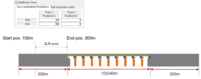 Figure 2. Example of Zero Longitudinal Resistance option
The bed placed between the rail and its support structure is modeled using elastic link types that have multi-linear curves in RSI Wizard. Therefore, the longitudinal stiffness of the elastic links in the ZLR zone will be 0 when the Zero Longitudinal Resistance option is applied.
The second one is the Rail Expansion Joints option. The rail expansion joint is installed to reduce additional stresses on the rail. To consider this option, input the specific location in which the rail expansion joint is located. If the user uses this option, the RSI Wizard will split the rail elements to create the joint position.
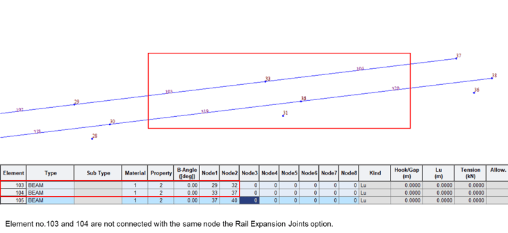 Figure 4. Rail Expansion Joints option
Section Tab
Once the layout information is set, we can move onto the Section tab. Here, the user can define the geometry section of a girder and a rail for each deck defined in the Layout tab. To assign a section to the deck and rail, the user can select one among sections defined in the section property feature. The ‘…’ button allows entering the section property feature to create other sections. For the section of rail, RSI Wizard provides 3 typical types(KS50, KS60, and UIC60).
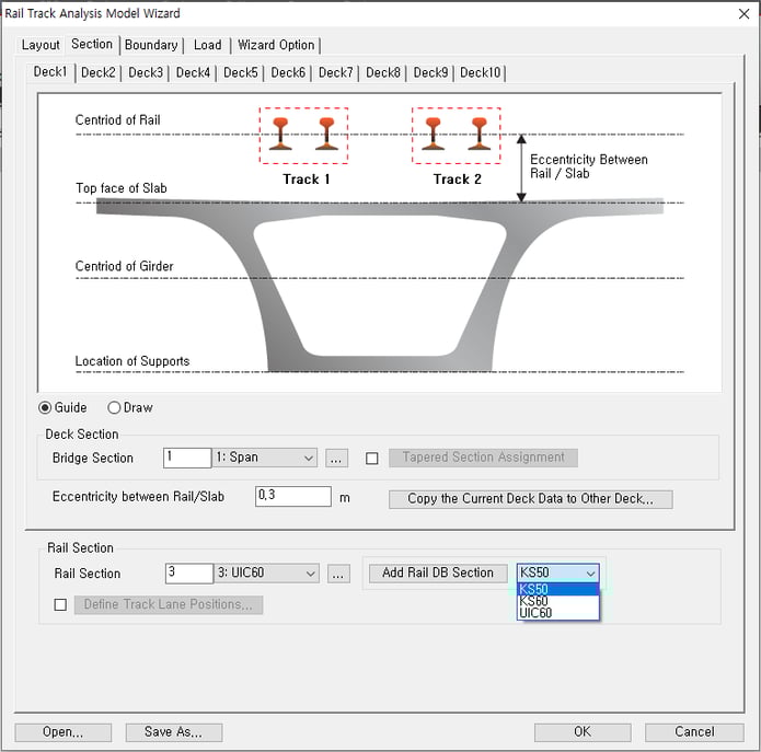
The Eccentricity between Rail/Slab option, Define Track Lane Positions, both options can control the location of tracks. The Eccentricity between Rail/Slab option sets the vertical position of elements for rails as shown in the figure below. The Define Track Lane Positions option sets the lateral position of rail elements. RSI Wizard allows creates two tracks, and the track can be symmetric arrangement or asymmetrical arrangement.
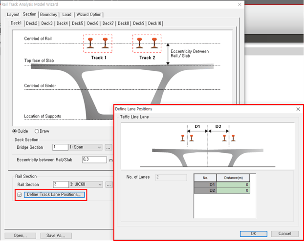 Figure 6. Define Track Lane Position option
Boundary Tab
After that, move onto the Boundary Data tab and set information about the boundary conditions. The user can define options to consider the resistance of the track to longitudinal displacement and boundary conditions of the model.
First, have a look at the Longitudinal Resistance Data option. RSI Wizard provides the bilinear function for the resistance of the track. The user can input values manually to define the character of the rails desired. The bed type is available for the ballast bed and concrete bed. If both bed types are used for the project, use the Advanced option in the Define Condition to assign bed types along the length.
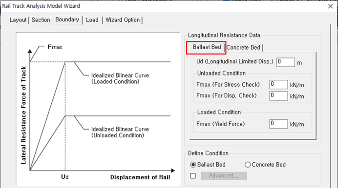 Figure 7. Longitudinal Resistance Data of Ballast Bed
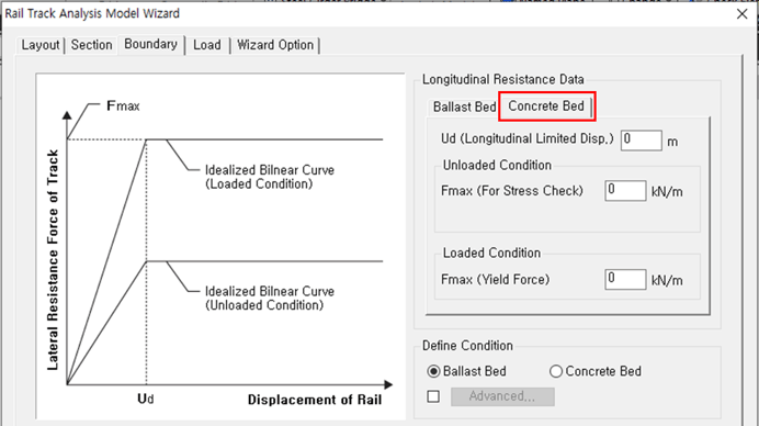 Figure 8.Longitudinal Resistance Data of Concrete Bed
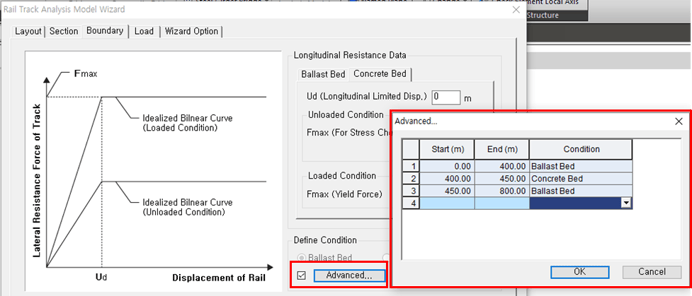 Figure 9. Advanced option of Longitudinal Resistance Data
The resistance of the track is per unit length. Therefore, the RSI Wizard calculates the stiffness of elastic link considering the length of elements and the resistance of the track inputted.
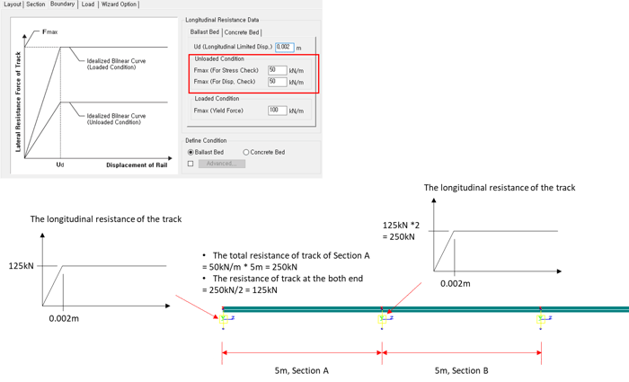 Figure 10. The calculation process of the longitudinal resistance of the track
The boundary option defines the boundary conditions of element models. It provides Spring and Bearing types. The essential input for both is horizontal stiffness. The Guide option shows the difference between the types, and also, the user can check the other boundary conditions in advance.
%20%26%20Bearing%20(right).png?width=709&name=Figure%2011.%20Boundary%20Types,%20Spring%20(left)%20%26%20Bearing%20(right).png) Figure 11. Boundary Types, Spring(left) & Bearing(right)
Figure 11. Boundary Types, Spring(left) & Bearing(right)
If the Spring type is selected, the deck's support will be considered as a point spring type. In the same manner, the Advanced option allows setting different stiffness at each point spring.
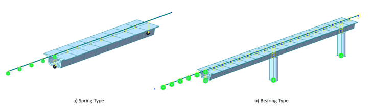 Figure 12. Actual model shapes
If the ‘Bearing’ type is selected, the RSI Wizard will create a model for the bearing and pier of a bridge. Bearings are modeled as elastic links, and pier structures are modeled as single columns with the same section. At the bottom of the pier, the user can apply fixed support or spring support. In the same way, if the ‘Advanced’ option is selected, the user can apply different elastic links, the length of the elastic link, and pier at each deck. Furthermore, the Guide option in the Boundary tab presents the model shape before generating a model to help users understand how a model shape will be created.
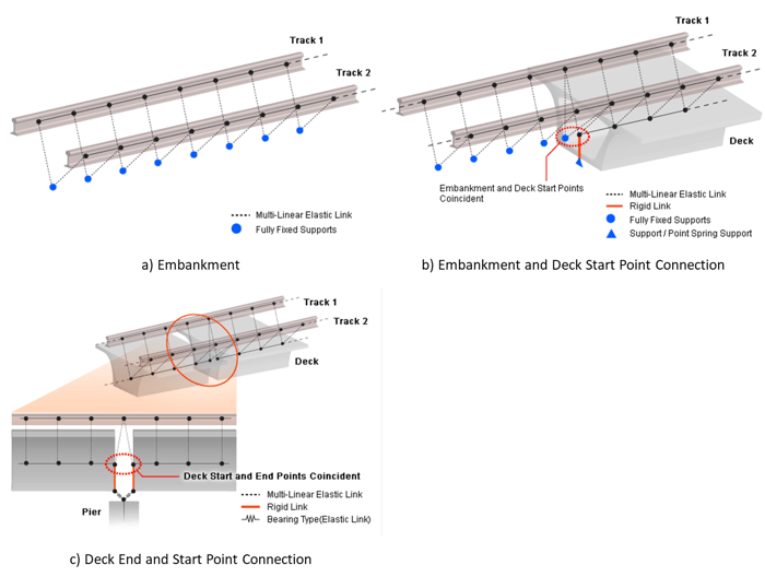 Figure 13. Detailed Model Shape
Load Tab
Once the Layout, Section, and Boundary information are defined, we can move onto the Load tab. Here, we can define load types that are needed for RSI analysis.
The first one is Temperature Load type. The user can input the magnitude of temperature for deck structures and rail to consider thermal expansion. If the deck structures have different material properties, click the Advanced Temp. option to define different temperatures for each material property. The unit of temperature load type provides Celsius and Fahrenheit. The type can be selected at the Unit System feature (Tools > Setting > Unit System).
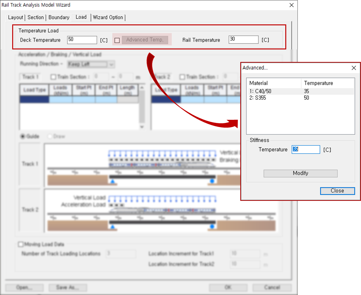 Figure 14. Temperature Load option
The second one is regarding the trainload. The user is able to define the magnitude of acceleration, braking, and vertical load in the table format. According to UIC 774-3, in the case of a bridge carrying two or more tracks, the acceleration forces on one track are added to the braking forces on the other track, and only two tracks need to be considered. The RSI Wizard allows defining the position of two tracks; therefore, the definition of loads is available for two tracks.
The direction of loads can be controlled using the Running Direction option. One-way direction, either Left or Right, can be selected for a structure having one track. If the structure has two tracks, loads with different directions will be applied to each track.
The trainload combines acceleration/braking loads and vertical loads. Each load needs its position to apply to a model. Especially, the length in which vertical loads are applied will be recognized as the length and location of a train. If the vertical load is not defined, Train Section should be set instead of defining vertical loads. In the section in which a trainload is applied, the resistance of the loaded track will be applied.
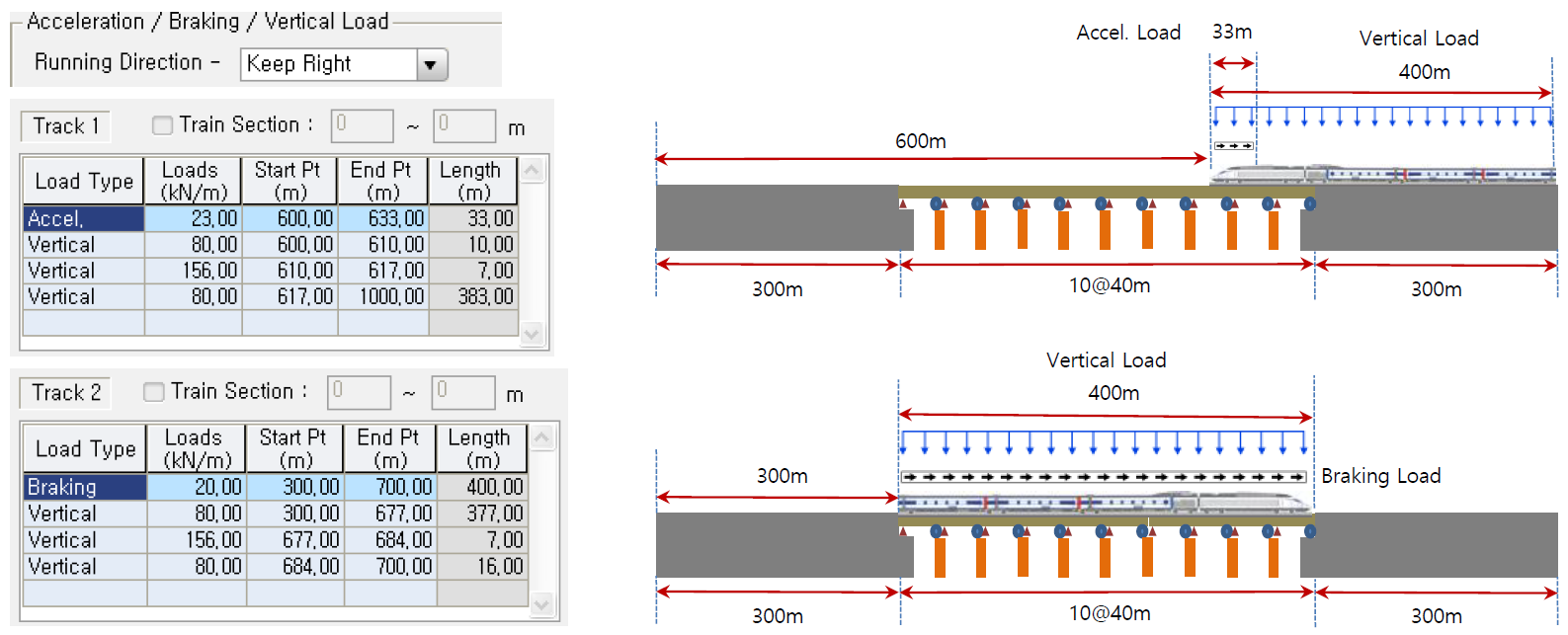 Figure 15. Example of Acceleration/Braking/Vertical Load
At the bottom of the Load tab, the user can find moving the Load Data. This option considers the movement of the train. The RSI wizard will create additional models depending on the number in the ‘Number of Track Loading Locations', and the increment magnitude of movement can be controlled by the ‘Location Increment for Track1’. For instance, if the user puts 3 in the Number of Track Loading Locations and 10 in the Location Increment for Track, 3 models with different train locations will be generated.
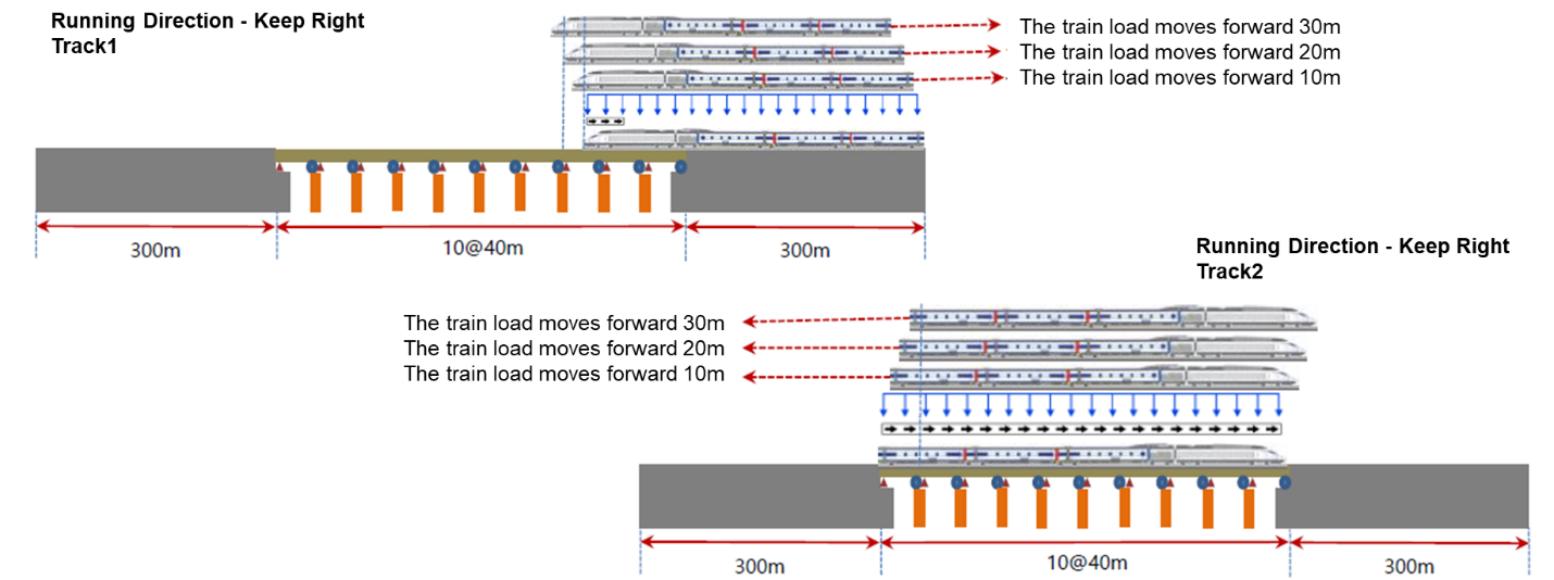 Figure 16. Example of Number of Track Loading Locations/Location Increment for Track 1&2 feature
Wizard Option Tab
The last step is to set information in the Wizard Option. The Wizard Option contains 3 options. The first one is the Modeling Option. This option splits the whole element model using an input in the Element Length. The user can select the unit as meters or feet.
According to the UIC Code, the analysis methods described below can be used for the track-bridge interaction analysis using the software. Depending on the software, either of the methods can be used. However, it should be noted that there can be errors between the two analyses.
1) Separate analyses for temperature variation, accelerator/brake load, and vertical load
Two or more nonlinear models having each load alone are analyzed and the results are combined. This is the simplest way of analyzing the rail-bridge interaction as it assumes that the superposition of the analysis results is allowed, which is normally not allowed in the nonlinear analysis. According to the UIC774-3 Code, generally 20%~30% larger stress can occur in the rail.
2) Staged analysis for temperature variation, accelerator/brake load, and vertical load
Construction Stage Analysis function of midas Civil is used. Before the train load is applied, the temperature load affects the structure. This initial displacement is reflected in the analysis in a stage when the train load is applied.
If a comparison is made between the two analyses, in general, the staged analysis reduces the compressive stress in the rail underneath the train as the yielding zone is larger in the staged analysis than the separate analysis. Therefore, the separate analysis overestimates the axial force because the resistance of the ballast at which train loading is applied is estimated to be the resistance under train loading plus the resistance under thermal loading, instead of the resistance under train loading alone.
midas Civil provides two modeling methods for RSI analysis. For checking stress results, the separate analysis method and the complete analysis method called the staged analysis method are available. For displacement result checks, a separate analysis method is available.
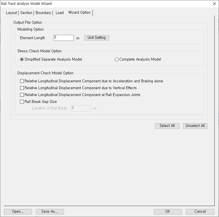 Figure 17. Wizard option of RSI Wizard
After clicking the OK button, the RSI Wizard generates model files depending on the options checked. The file names are shown below:
A. Stress Check Model Option
- Simplified Separate Analysis Model
- xxx_Temp.mcb
- xxx_Train.mcb
- Complete Analysis
- xxx_Complete.mcb
- xxx_Complete.mcb
B. Displacement Check Model Option for Separate Analysis Method
- Relative Longitudinal Displacement Component due to Acceleration and Braking Alone
- xxx_Add1_RelativeDisp.mcb
- Relative Longitudinal Displacement Component due to Vertical Effects
- xxx_Add2_RotationAngle.mcb
- Relative Longitudinal Displacement Component at Rail Expansion Joints
- xxx_Add3_ExpansionJoint.mcb
- Rail Break Gap Size
- xxx_Add4_RailBreakGapSize.mcb
Rail Track Analysis Report
RSI Wizard contains the Rail Track Analysis Report, which is a post-processing feature. Rail Track Analysis Report is used to analyze all the models and obtain the compiled excel file. It provides a final summary sheet with checks based on UIC 774 - 3. These check limits are manually modified for regional codes. This report wizard could only be used with the Simplified Separate Analysis option. The Complete Analysis Model is not supported for the report. The report will contain tabulated data as well as graphical output for individual rail stresses, rail and deck relative displacements as well as deck absolute displacements. An example of the results is shown below.
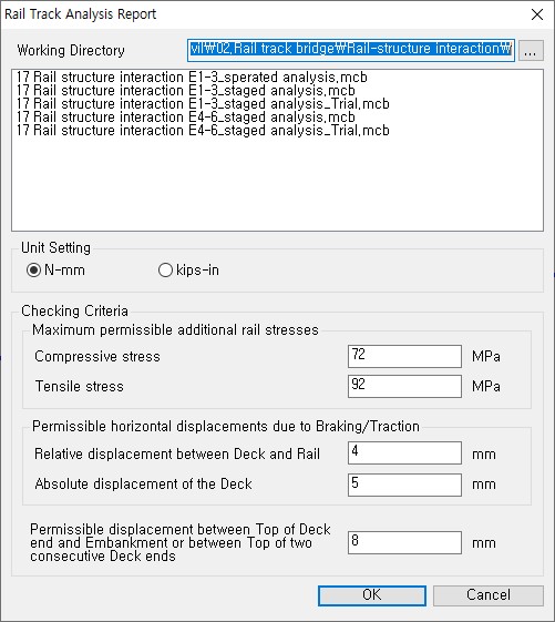 Figure 18. Rail Track Analysis Report Feature
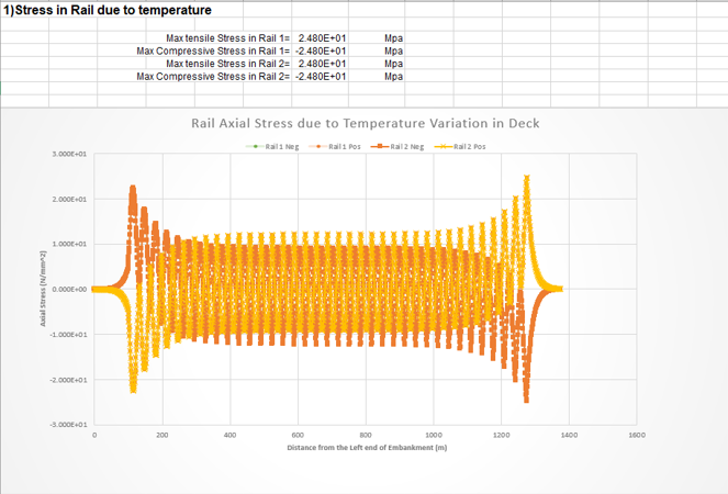
Figure 19. Stress in Rail due to Temperature
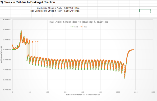 Figure 20. Stress in Rail due to Braking & Traction
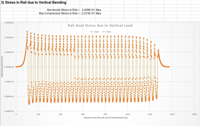 Figure 21. Stress in Rail due to Vertical Bending
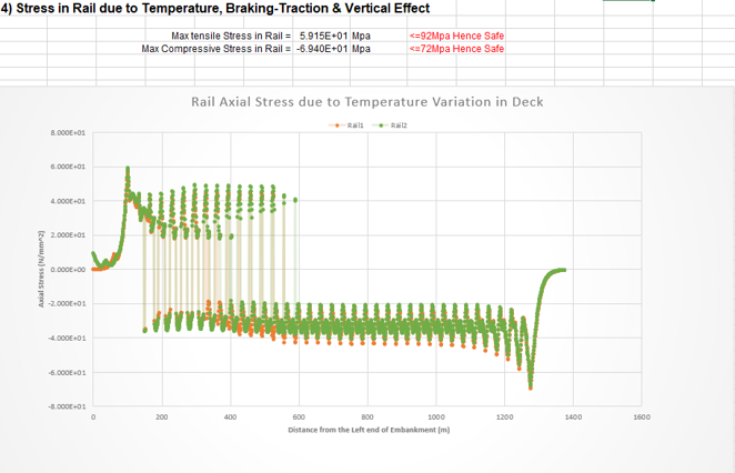 Figure 22. Stress in Raile due to Temperature, Braking-Traction & Vertical Effect
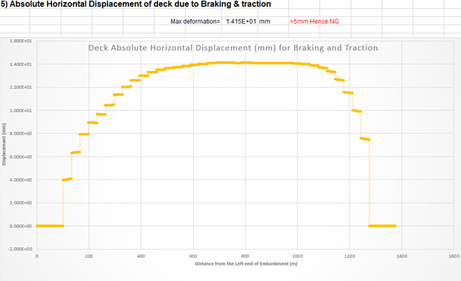 Figure 23. Absolute Horizontal Displacement of the deck due to Braking & Traction
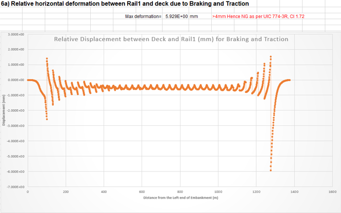 Figure 24. Relative horizontal deformation between Rail1 and deck due to Braking and Traction
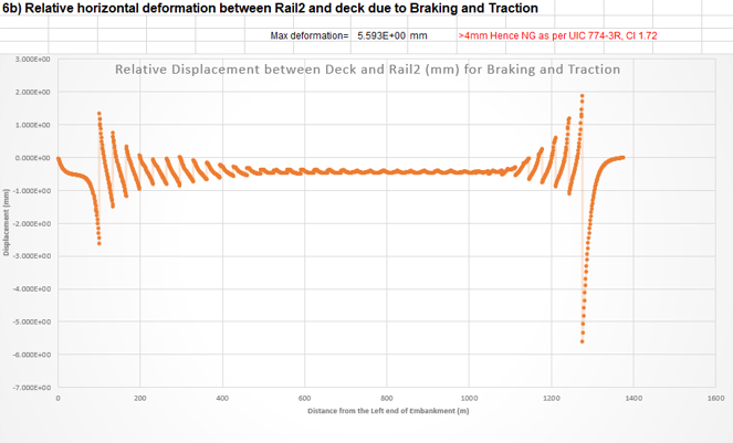 Figure 25. Relative horizontal deformation between Rail2 and deck due to Braking and Traction
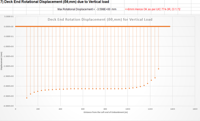 Figure 26. Deck End Rotational Displacement due to Vertical load
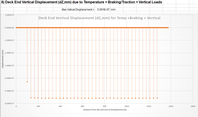 Figure 27. Deck End Vertical Displacement due to Temperature + Braking/Traction + Vertical Loads
Summary
1. midas Civil provides the Rail-Track Wizard for RSI analysis.
2. The Rail-Track Model Wizard generates models considering the Simplified Separate Analysis method and Stage Analysis method. And also, it includes information about essential inputs.
3. The Rail-Track Analysis Wizard generates a result report using model files created by the Rail-Track Model Wizard.


.png)
/Seismic%20Design%20of%20Concrete%20Bridges/Seismic%20Design%20of%20Concrete%20Bridges%20345%20240.png)
/Geometry%20Modeling%20Techniques%20for%20Bridge%20Engineers%20Seeking%20for%20More/Geometry%20Modeling%20Techniques%20for%20Bridge%20Engineers%20Seeking%20for%20More.png)