 Get Started midas Civil
 Featured blog of this week


Please fill out the Download Section below the Comment Section to download the Complete Guide to Composite Sections

1. Introduction and History
The construction industry is evolving at mind-blowing speed. Using the latest available technology and software solutions is essential to reduce the efforts of engineers. With more accurate modelling of structures, their design are becoming much more efficient and cost effective. The aim of structural design is to design a structure so that it fulfils its intended purpose during its intended lifetime with adequate safety (in terms of strength, stability and structural integrity), adequate serviceability (in terms of stiffness, durability, etc.) and economy. The development of Load and Resistance Factor design (LRFD) methodology and the transition from Allowable Stress Design is an excellent example of the innovation and progress happening in the civil engineering.
Let’s start with a bit of a history here. In the 1900s, the building design and construction process began to formalize codes and requirements.
In 1931, AASHTO issued “Standard Specifications for Highway Bridges” that was based on Allowable stress design methodology.
American Concrete Institute (ACI), pioneered and adopted a methodology that both incorporated load factors and considered the ultimate stress, rather than allowable stress, as an alternate and more rational strategy for design.
In 1956, ACI introduced LRFD (then called Ultimate Strength design) in ACI 318, the "Building Code Requirements for Reinforced Concrete".
In 1963, Working stress and Strength methods achieved separate but equal status within the body of ACI 318.
In 1979, the Ontario Ministry of Transportation released the “Ontario Highway Bridge Design Code”, which was the first reliability-based limit state specification in North America.
In 1986, AISC introduced LRFD in “Load and Resistance Factor Design Specification for Structural Steel Buildings”.
In 1994, AASHTO published the first edition of LRFD in both customary U.S. and SI units
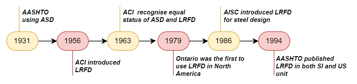 Fig 1 Timeline LRFD
2. Allowable Stress Design | Working Stress Design
Allowable Stress Design or Working Stress Design or Permissible Stress Design all refers to the same methodology.
This approach has been used by civil engineers since the early 1800s. The civil designer ensures that the stresses developed in a structure due to loads do not exceed the elastic limit. This limit is usually determined by ensuring that stresses remain within limits through the use of factors of safety.
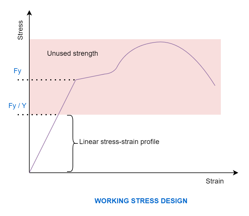
Allowable stress design method is based on linear elastic material models. That means the stress-strain curve is linear for all the material, whether it is steel or concrete. ASD method results in stronger structure for more predictable loads
The method primarily assumes that the structural material behaves as a linear elastic manner and that an adequate safety can be ensured by suitably restricting the material stresses induced by the expected “working loads” on the structure. As the specified permissible stresses are kept well below the material ultimate strength, the assumption of linear elastic behavior is considered justifiable. The ratio of the strength of the material to the permissible stress is often referred to as the “factor of safety.” There are some obvious issues with this assumption of linear elastic behavior and also the assumption that the stresses under working loads can be kept within the “permissible stresses.”
A lot of factors may be responsible for inadequacy of these assumptions, e.g., long-term effects of creep and shrinkage, the effects of stress concentrations, and other secondary effects. This design approach usually results in relatively large sections of structural members, thereby being conservative and providing better serviceability performance under the usual working loads.
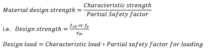
In ASD, the uncertainties in the calculations of loads and resistances are accounted for through a single global Factor of Safety. i.e. when more than one source of load is acting, the load effect Q is calculated as the direct sum of the best estimation of the separate effects. A critical drawback of this approach is that all uncertainty is lumped into one global factor, which leads to inconsistent margins of safety for different scenarios.
3. Limit State Method | Load and Resistance Factor Design
Limit State design is an advancement over ASD. LRFD is based on sound principles and a coherent approach for ensuring safety, serviceability, and economy. This approach, unlike ASD, aims for a comprehensive and rational solution to the design problem, by ensuring safety at ultimate loads and serviceability at working loads. This philosophy uses more than one safety factor attempting to provide adequate safety at ultimate loads as well as satisfactory serviceability performance at service loads, by considering all possible failure modes.
The term “limit state” refers to a state of impending failure, beyond which a structure ceases to perform its intended function satisfactorily, in terms of either safety or serviceability i.e., it either collapses or becomes unserviceable.
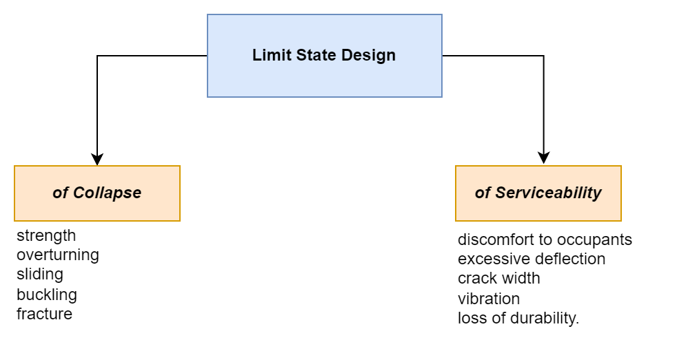
There are two types of limit states:
(1) Ultimate Limit States which deal with strength, overturning, sliding, buckling, fatigue fracture, etc.
(2) Serviceability Limit States which deal with discomfort to occupancy and/or malfunction, caused by excessive deflection, crack width, vibration leakage, and loss of durability.
AASHTO LRFD addresses four limit states: strength, serviceability, fatigue, and extreme events.
LRFD results in a stronger structure for dynamic loads.
4. Example
Let’s understand the difference between the two by designing a simple beam with UDL loading. Here, we will be designing a singly reinforced simply supported beam with Live load of 10kN/m. For simplification, Self weight is ignored here. We will only be observing how the depth changes for the same load requirement.
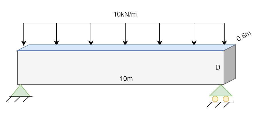 Fig 5 Example Beam
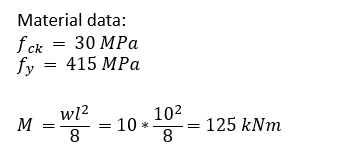
Assume effective cover = 30mm
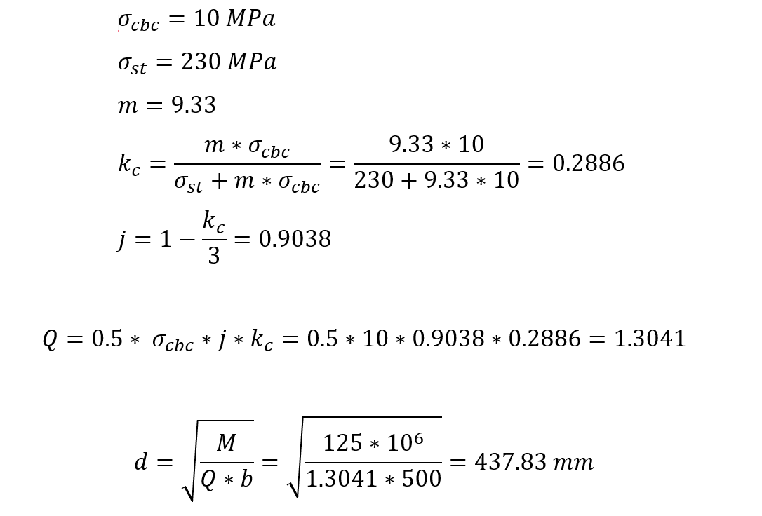
Working Stress Method
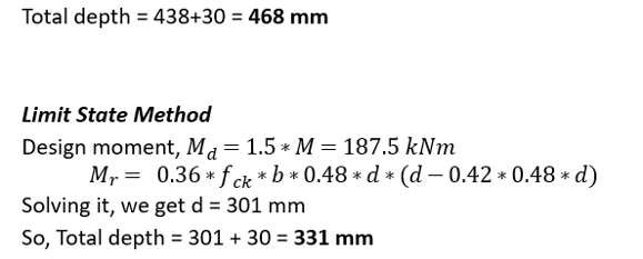
5. Conclusion
So at the end of the day, the working stress method and the limit state method are two key approaches used in structure design. The working stress approach, which was frequently employed in the past, was focused on maintaining stresses in a structure below a certain level. However, it was later superseded by the limit state method, which considers not just a structure's strength but also its stability and serviceability. The transition from the working stress method to the limit state method has resulted in a more complete and dependable approach to structural design, assuring the safety and longevity of our built environment.
👉To see related contents, please click on the tags under the Topic section below.


.png)


/Static%20Analysis%20of%20Cable-Stayed%20Bridges/Static%20Analysis%20of%20Cable-Stayed%20Bridges%20345%20240.png)