 Get Started midas Civil
 Featured blog of this week

Check out our previous blog post, where we discuss 2D and 3D Analysis of Culverts.
We've provided the link here for your convenience [click].
Table of Contents
*Click the content to move to the section
1. Overview
2. Key Considerations
3. Creating a Structural Analysis Model
4. Conclusion
1. Overview
Culvert refers to a structure that is installed under a structure for the purpose of allowing water to pass or pedestrian traffic, and it means that the ceiling is not open. Among them, the structure type where the ceiling is open for water is separately called an open culvert.
Culverts can be divided into the following two categories depending on their purpose of use:
|
💡 Culvert classification by purpose of use
|
Culverts are composed of a square section with a hollow center, as shown in the figure below, and have a haunch. They are referred to as 1-cell culverts, 2-cell culverts, 3-cell culverts, etc., depending on the number of openings in the center.

Various design standards provide information on the design of culverts, such as the Road Culvert Structure Design Standard.
In this article, we will look into necessary consideration notes regarding design when creating culvert models by 1D beam elements.
2. Key Considerations
The design of a culvert involves determining the amount of reinforcing steel by examining the moment and shear force of the structure. It is common to create a structural analysis model using 1D elements (Beam elements) through midas Civil to calculate the member forces and check the safety of reinforcing steel using UMD.
When creating a structural analysis model using 1D elements (Beam elements), the following should be considered:
- Analysis plane setting: Since the culvert model is analyzed in a 2D plane, the analysis plane must be set beforehand.
- Aligning local coordinate systems of the structural members: To apply loads and obtain consistent analysis results, the local coordinate systems of each element must be matched.
- Boundary condition setting: To prevent errors in applying springs that describe the ground, lateral constraints must be arbitrarily applied.
- Rigid End setting: To adjust for areas with high rigidity, such as the haunch, rigid end settings must be performed.
👉You can refer to our previous blog post about Culvert Rigid End Distance Calculation (click)
- Load combination: Since errors can occur in the analysis results when analyzing each load individually, an analysis case that considers all loads must be created.
Basically, when modeling a culvert using 1D elements (Beam elements), consideration must be given to the above three items.
3. Creating a Structural Analysis Model
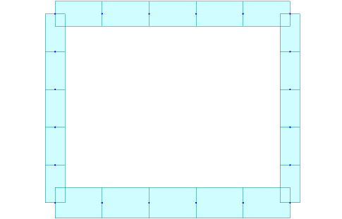
Creating a 1D element (Beam element) using midas Civil can be done simply by entering values on the GUI. You can refer to the attached tutorial for creating the modeling. The concrete material used for modeling is C27, and the dimensions used for the upper slab are 0.7mx1.0m (HxB), for the wall 0.55mx1.0m (HxB), and for the lower slab 0.85mx1.0m (HxB).
The generated modeling is shown below.
Now, let's go through some points to keep in mind when creating a structural analysis model.
1) Setting up the analysis plane
When analyzing a culvert, instead of modeling the entire culvert, it is modeled as a unit length model and analyzed using 1D beam elements.The structure is modeled on the X-Z plane, assuming that the structure exists continuously in the Y-direction.
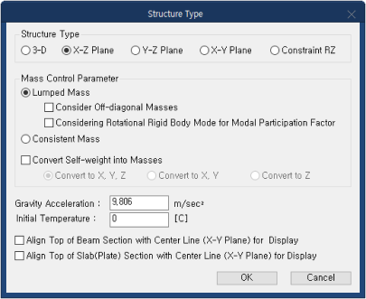
Since midas Civil performs 3D analysis by default, if Y-directional displacement and Z-axis rotational displacement are not additionally constrained, the structure becomes unstable and a Singular Error occurs. Therefore, it is essential to specify that the structural analysis is performed on a 2D plane.
In midas Civil, this can be easily set up in the Structure Type section under the Structure tab. By selecting the modeled plane in Structure > Type > Structure Type, unnecessary boundary conditions are automatically constrained when 2D is selected. Therefore, users only need to define boundary conditions associated with 2D analysis. For example, if the X-Z plane is selected, Dy, Rx, and Rz are automatically constrained.
By setting up the analysis to be performed on the X-Z plane in the dialog box shown below, these issues can be resolved.
2) Setting local coordinate system for members
In midas Civil, analysis results are output based on the element coordinate system, so all element coordinate systems must be aligned to obtain consistent analysis results. To change the characteristics of elements, you can use the "Change Element Parameters" function to change the local coordinate axis of the desired member at once.

3) Boundary condition settings
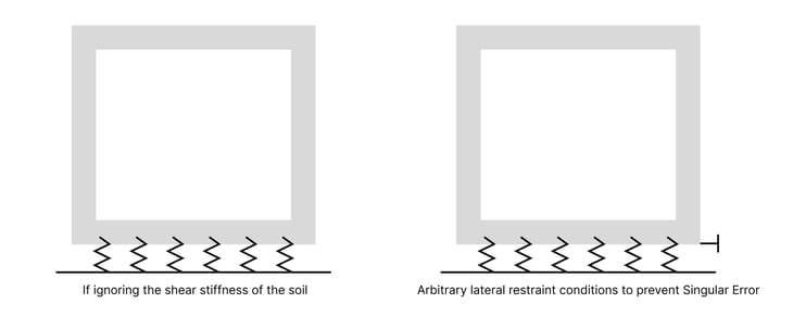
Culvert structures have soil present both inside and outside of the structure, and if ignoring the shear strength of the soil, the boundary conditions can be established by applying soil reaction coefficients to the culvert's lower slab as shown on the left in the figure below.
For rock structures, there is both an underlying and an external soil layer. If the shear strength of the soil is ignored, the boundary condition can be set by applying the subgrade reaction modulus to the lower slab of a culvert, as shown on the left in the figure below. However, in this case, there is no horizontal boundary condition, which can lead to a Singular Error and produce unreliable results.
Therefore, a lateral boundary condition should be applied at an arbitrary point to prevent Singular Error. It is important to note that this boundary condition does not actually exist, so after the analysis, the reaction force must be checked. The reaction force value should be close to zero or zero to have no effect on the structural system. If a large lateral reaction force occurs, the location where the boundary condition was applied should be modified or the design conditions, such as the load, should be checked again.
4) Setting up Rigid End
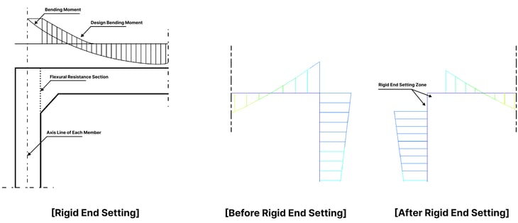
According to the road bridge design standards KDS 44 90 00, it is specified that "The effect of the flexural stiffness due to the haunch and the change in member axis caused by it were negligible in structural analysis, so they were ignored." In this case, the bending moment acting on the member's end points is as shown in the figure below.
The calculation of such rigid end must be done according to the method prescribed in the road bridge design standards. Of course, midas UMD provides a calculation of rigid end distances, so it is possible to calculate the rigid zone distance simply by entering basic member information.
In midas Civil, rigid end can be considered using Beam End Offsets. In this case, the member's starting point is denoted as i, and the end point as j, and the rigid zone distance can be applied accordingly. Before applying the rigid zone, it is necessary to confirm the starting and ending points based on the local axis of the member.
The distribution of the moment before and after setting up the rigid zone is shown below.
4) Load Combination
Load combinations should be performed by applying appropriate coefficients according to the design standards being applied. Structural analysis performed in midas Civil calculates the results of individual loads separately and then linearly superimposes the results of the member forces generated by each load, taking into account the load coefficients, to obtain the final results of the load combination. Therefore, reliable results must be obtained from all conditions in which individual loads are analyzed.
Generally, underground structures are in the form of being placed on the ground, and the ground can only resist the gravity direction load and cannot resist any load in the opposite direction of gravity. Therefore, the boundary conditions of the ground input for underground structures are simulated using Comp. Only Type Point Spring Support or Elastic Link. A model with nonlinear boundary conditions such as Comp. Only Type Point Spring Support/Elastic Link finds the state in which all springs are compressed by repeating the analysis. Therefore, if all springs are compressed within the set number of iterations, the results will converge, but if not, the results will diverge, and unreliable values will be output.
Since underground structures such as rock anchors are subject to boundary conditions using Comp. Only Type Point Spring Support or Elastic Link, there are cases where abnormal behavior may occur due to the applied loads such as positive pressure or non-uniform loads.
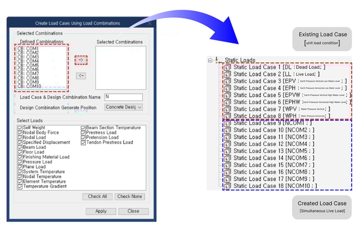
To eliminate these errors in the analysis, midas Civil provides a function to replace the loads in the load combination with simultaneous point loads based on the generated load combination.
When using the "Create Load Cases / Using Load Combinations" function, all loads included in the load combination are changed to one load condition that is simultaneously applied, so structural analysis can be performed without errors.
4. Conclusion
Although Culverts are simple structural types, but many factors need to be considered according to each design standard.
Using midas Civil, you can easily and conveniently proceed with the design, but due to the characteristics of the culvert structure and the Beam element, you must always check the following matters and proceed with the design.
- Analysis plane setting: Since the culvert model is analyzed in a 2D plane, the analysis plane must be set beforehand.
- Aligning local coordinate systems of the structural members: To apply loads and obtain consistent analysis results, the local coordinate systems of each element must be matched.
- Boundary condition setting: To prevent errors in applying springs that describe the ground, lateral constraints must be arbitrarily applied.
- Rigid End setting: To adjust for areas with high rigidity, such as the haunch, rigid end settings must be performed.
👉You can refer to our previous blog post about Culvert Rigid End Distance Calculation (click) - Load combination: Since errors can occur in the analysis results when analyzing each load individually, an analysis case that considers all loads must be created.
Also, these five points should be considered and checked at least once when designing culverts or performing analyses using Beam elements for underground structures, not only for culverts.
In midas Civil, there is a Wizard that makes modeling easier and provides various functions. In the next content, we will introduce the Rahmen/Culvert Wizard function, which allows for easier design and generation of structural calculation reports for culverts and frames.
👉To see related contents, please click on the tags under the Topic section below.


.png)

/Static%20Analysis%20of%20Cable-Stayed%20Bridges/Static%20Analysis%20of%20Cable-Stayed%20Bridges%20345%20240.png)