Get Started midas Civil
 Featured blog of this week

Elongations of Prestressing Steels
When we build prestressed concrete structural members, which is a frequently used material for bridges worldwide, the benefit in material savings and reduction of dimensions is guaranteed only when it is built correctly. Structures behave the way they are built, and not the way they are designed, so it is imperative that the designer and reviewer engineers provide the necessary information so that the construction process is oriented towards a structure that meets all safety requirements.
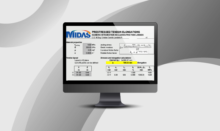
In this article, we present, in a concise way, the reasons why the elongations of prestressing steels in bridges should be controlled, and in the end, we provide a comparison of a real case in contrast to what is obtained from numerical modeling. Also, you can download a spreadsheet template (Click here) for the manual calculations of the friction loss and elongations that you can use to compare with the reliable results of midas Civil.
Table of Contents
1. What Physical Phenomena are Involved in the Elongation of Prestressing Steel?
Thanks to Physics, we know that, if we subject a material to any force, internal deformations will occur in it. When these deformations are due to a tensile force, the element will lengthen, and when we talk about prestressing steel in bridges, those deformations are called elongations.
Figure.2 Hooke's law highlighting the effect of tensile forces
Naturally, the elongations of prestressing steel on bridges that are built with a bonding mechanism are reduced by the effect of friction between the steel and the surrounding surface. In the case of post-tensioning, this surface is usually a metal corrugated duct that provides the path of the cables within the concrete element. This article will focus on the post-tensioned case of prestressed concrete with bonded tendons as a general reference to any form of prestressing steel.
Considering the above two phenomena, we can conclude that there will be other variables that can directly or indirectly affect elongations. For example, a straighter path will have less friction than a less curved path, and therefore there will be more elongation for the same applied tension force.
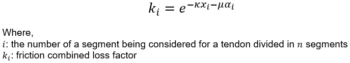
Ignoring the mathematical procedures involved, it is easy to derive the equations used to compute the force or stress at the end of a tendon subjected to friction:
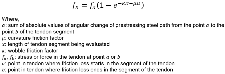 Equation 1 Friction loss for a prestressed tendon segment
The previous equation can be found in most design codes and literature regarding prestressed concrete members, but it was simplified and generalized for the friction problem in this article. For a more complete study of the friction problem the reader is encouraged to read Prestressed concrete analysis and design: fundamentals (2012), by Naaman. The graphic interpretation of these variables is shown below in a loss graph of midas Civil.
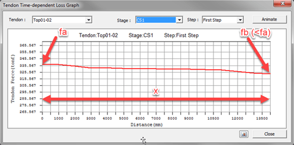 Figure 3 Example of a prestress loss graph including friction loss
If we look at Equation 1, a quick observation is that the friction can be combined in a general factor in a convenient way:
 Equation 2 Friction combined loss factor for a prestressed tendon segment
Finally, if we introduce deformation compatibility to the equations and perform numeric integration, the tendon elongation can be computed using the following equation:
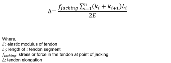
This last equation is very handy to perform manual calculations of elongation of prestressing steels in concrete. Also, this is the equation used in the example of this article and in the spreadsheet template that can be downloaded.
2. Is it Important to Control Elongations?
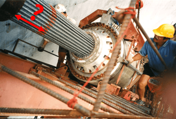
During the prestressing process, and especially in post-tensioned elements, it is important to measure the elongation of cables to control the induced stresses in the prestressing steels.
It is necessary to control the elongation because:
• This is an indirect control of the stresses in the prestressing steel.
• It allows to limit the speed of the prestressing application to avoid any dynamic load effects.
• This allows setting the minimum required prestressing equipment capacity.
• It provides indicators that may help to prevent possible problems from occurring during the jacking process.
• This allows adjusting the logistics of the prestressing works.
During the jacking process, differences between estimated (theoretical) and measured (in-situ) elongations may occur. There will be differences always as it happens with most theoretical calculations when compared with reality, but in this case, if these differences are very large, we may be facing different constructive problems. For example, if there is a jam inside the duct of the prestressing steel, the design tension force may be achieved but may not be properly transmitted to the opposite anchorage point and so, the elongation will be much smaller than the estimated value. In these cases, it will be necessary to follow these steps:
1. Stop the prestressing process and record the last prestressing force and elongation.
2. Verify the elastic behavior of the prestressing process. As both force and elongation are recorded, it is important to ensure that the cable remains elastic and has not undergone any nonlinear behavior like yielding.
3. Estimate the location of the jam inside the prestressing steel duct. This can be accomplished by isolating the length variable from the friction equation and using the measured elongation as an input. The resulting length will be the approximate location of the jam in the duct.
4. The jam should be fixed considering the type of element where the problem was found and whether the cable can be temporarily removed when implementing the solution.
5. Once the jam has been fixed, the prestressing works can continue starting with this cable.
Important note: this is a general procedure for assessing these types of problems and cannot replace a complete evaluation from a competent engineer in the context of the situation.
Some design and construction codes and guides had established an allowable difference between the estimated and measured elongation. In the case of the American Concrete Institute, table 4.4.4.4 of the ACI 423.10R-16 guide summarizes some of these tolerances according to different international codes:
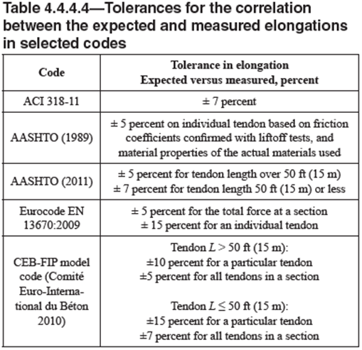
Some interesting conclusions can be found:
• In general, the tolerances are low, ranging from 5 to 7% in most cases.
• Tolerances for shorter tendons are higher than that for longer tendons.
• Some codes not only study the tolerance for a particular tendon but for the entire section.
In the case where measured elongations fall outside the given tolerance, we should perform an evaluation that is adequate for the specific project being built. The first objective will be to find the reason for the discrepancies and the second will be to propose a solution to the problem. One method to achieve the first objective is to perform in-place friction tests, as required in commentary C5.9.3.2.2b of AASHTO LRFD 2020. Further discussion on handling these issues is presented in the AASHTO LRFD Bridge Construction Specifications.
The answer is a plain and direct yes. In midas Civil, for example, all the necessary parameters can be entered to accurately determine the elongations of the tendons. In addition, the program also allows representation of the prestressing steel through the tendons function, which makes it possible to enter the tendons' layout in detail.
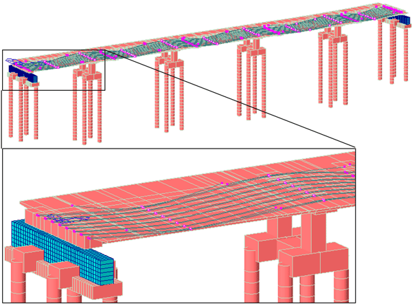
Figure 4 Model of a continuous prestressed bridge. Cables implemented as tendons are highlighted
The most useful thing about estimating elongations through numerical models is that it can face cases of complicated geometries, starting with three-dimensional layouts, like in the case of in-plan curved box bridges or with inclined webs.
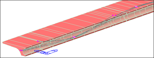
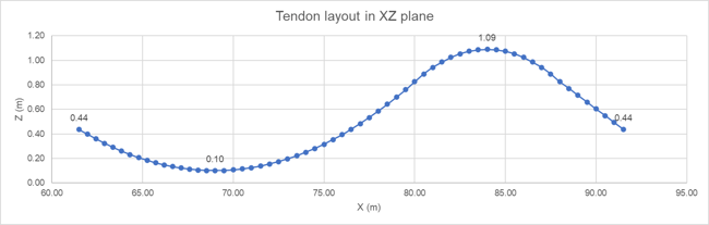
Considering the continuous prestressed bridge shown in the previous chapter, let's analyze one of its segments assuming that it is constructed span-by span. Now, for a typical span, the cable layout for the XZ plane in one of the inclined webs is shown below:
|
σ0 (MPa) |
1430 |
Jacking stress |
|
Ε (GPa) |
200.00 |
Young modulus |
|
μ (rad-1) |
0.25 |
Curvature friction factor |
|
κ (m-1) |
0.0025 |
Wobble friction factor |
The XY cable layout is not given because it is usual in practice to perform manual calculations only considering the vertical plane layout. Using Equation 1, the stresses along the tendon can be found. Those stresses are superposed with the tendon layout in the following figure:
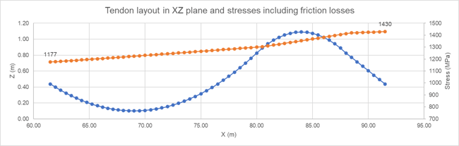
Now, Equation 3 can be used to estimate the theoretical tendon elongation, which results in 194,02 mm. Remember that this result only considers the XZ layout (2D). Finally, using the midas Civil program to estimate it with the 3D real layout, a value of 190,60 mm is obtained:
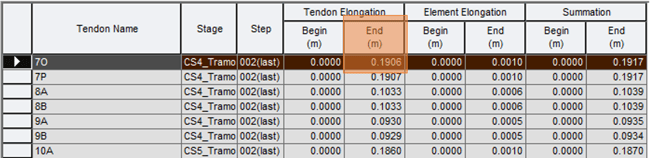
The estimation of midas Civil program is very accurate. Taking this result as the best estimation of the elongation, we find that the manual calculation has an error of 2%. However, recalling the tolerance values of AASHTO codes, we would only have a 5% allowable difference between the estimated and measured elongation for this cable of approximately 30 meters in length. This means that, if we use the manual calculation, we will only have a remnant of 3% left to absorb the constructive tolerance!
5. Test your Knowledge and Reflect
Answer the following questions in the comments section below and test your knowledge:
1. In the previous exercise, we did not mention which was the jacking end of the cable (i.e. the point where the prestress is applied). Using the information given, which is this jacking end and why?
2. It is evident that all the projects are different from each other. Do you think it's important to control elongations in conventional prestressed concrete bridge projects?
3. Are there other factors that can influence the difference in elongations?
6. References
• American Association of State Highway and Transportation Officials, AASHTO. AASHTO LRFD Bridge Design Specifications, 9th Edition (2020).
• Naaman (2012). Prestressed concrete analysis and design: fundamentals.
• American Concrete Institute (2016). ACI 423.10R-16 Guide to Estimating Prestress Loss.