Get Started midas Civil
 Featured blog of this week


🗂️ Download Now
Please fill out the Download Section below the Comment Section to download the Full Webinar PDF File

Prestressed concrete (PSC) box girders are considered one of the most flexible forms of the bridge deck. For spans above 50 meters, PSC Segmental Box Girder Bridges are the economical choice. The webinar discusses PSC Box Girders and PSC Segmental Bridges. Notable construction methodologies for PSC Segmental Box Girder Bridges are also shown in the webinar. Lastly, a short demonstration is shown of using MIDAS CIVIL highlighting model creation, analysis, and design.
🔑 Key Points
1. What are PSC Box Girders?
Prestressed concrete (PSC) box girders are concrete sections following a boxed shape supported by prestressed strands. Their inherent high torsional resistance, economy, and lower overall maintenance costs make them very attractive in highway and railway construction.
2. Segmental PSC Bridges
Segmental PSC bridges involve the assembling of smaller pieces (called ‘segments’) using post-tensioning tendons. The challenge in these types of bridges is that the means of construction significantly affect the bridge's design.
3. PSC Segmental Bridges using MIDAS CIVIL
The webinar demonstrates the use of the MIDAS CIVIL FCM wizard to create a sample model. Viewing analysis and design results are also shown in the webinar.
1. What are PSC Box Girders?
Prestressed concrete (PSC) box girders are concrete sections forming a boxed shape (rectangular or trapezoidal) supported by prestressed strands. These girders are widely used for footbridges, highway bridges, and railway bridges. They offer a significant reduction in self-weight for longer spans and have high inherent torsional stiffness.
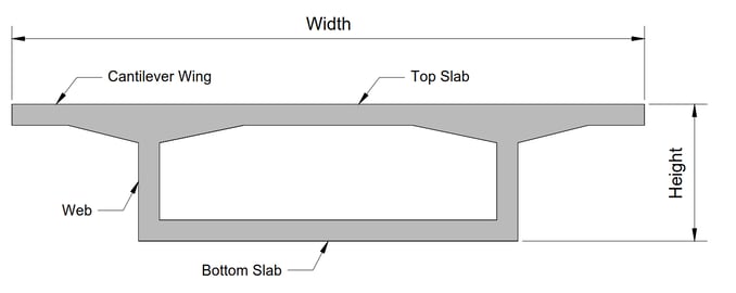 Figure 1. Single-Cell Box Girder Cross-Section
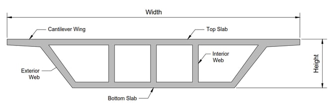 Figure 2. Multi-Cell Box Girder Cross-Section
Box girders are considered one of the most flexible forms of the bridge deck. Box girders allow an economical range of spans from 30 meters to 300 meters (non-suspended). They are also able to accommodate decks that are up to 30 meters wide. They are also aesthetically pleasing, with a reduced number of required supporting piers.
2. Segmental Box Girder Bridges
A segmental PSC bridge is built in small sections (called segments). Single or multiple-cell box sections are generally used for the superstructure. The segments may either be cast-in-situ or precast/prefabricated. The post-tensioning system can be bonded, unbonded, or a combination of both.
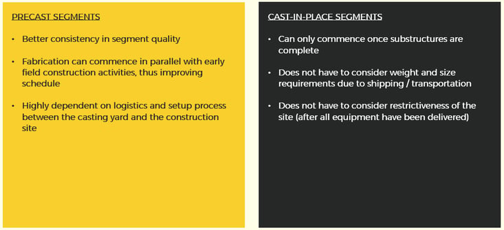 Figure 3. Precast vs Cast-in-Place Segments
3. Construction Methodologies
A vital factor to consider when working on segmental bridges is that it is critical to determine the construction means and methods. The construction approach dramatically affects the design, such as the tendon layouts. Construction loads are also a significant factor in the design. Some notable construction methods for segmental box girders are Balanced Cantilever Construction / Free Cantilever Method, Incremental Launching, and Span-by-Span Construction.
.png?width=733&name=Balanced%20Cantilever%20Construction%20(figure%20showing%20Cast-in-Situ%20Segments).png) Figure 4. Balanced Cantilever Construction (figure showing Cast-in-Situ Segments)
Figure 4. Balanced Cantilever Construction (figure showing Cast-in-Situ Segments)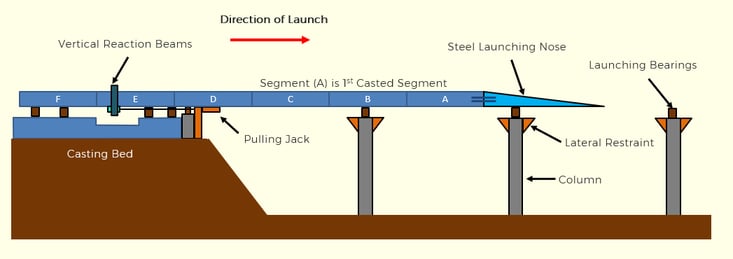 Figure 5. Incremental Launching Method
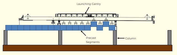 Figure 6. Span-by-Span Construction
4. Design Considerations
The PSC Segmental Box Girder bridge design starts with the Conceptual Design, where the configuration and span arrangement of the bridge are determined. Longitudinal Design is then the verification of the sections at the relevant limit states. Flexural Strength, Shear and Torsional Strength, and Serviceability requirements along the length of the bridge are rigorously checked. The Transverse Design is also carried out, factoring in the complex mix of forces the box girder will have to resist. A two-dimensional plane frame of unit length is often used in analysis due to its simplicity against the more tedious three-dimensional analysis.
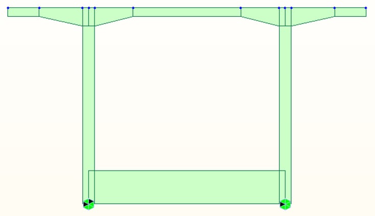
Figure 7. 2D Transverse Analysis Model for a PSC Box Section
The Construction Stage Analysis is checked in parallel with all design stages to ensure that all elements of the bridge will have sufficient strength and stability at all times.
5. Using MIDAS CIVIL
MIDAS CIVIL has various features that can be used to model, analyze, and design PSC Segmental Box Girder Bridges. To name a few, see the figure below.
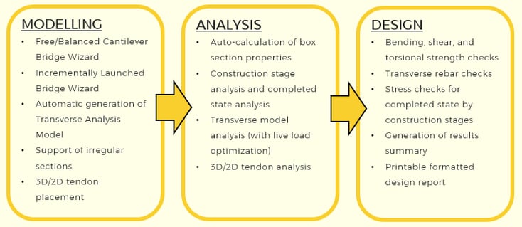 Figure 8. Some of the most notable MIDAS CIVIL features for PSC Segmental Box Girder Bridges
The webinar shows how to create, analyze, and design a segmental bridge via balanced cantilever construction. The summarized steps are:
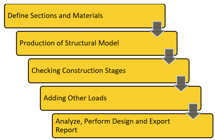 Figure 9. Summary of BC Bridge Procedure using MIDAS CIVIL
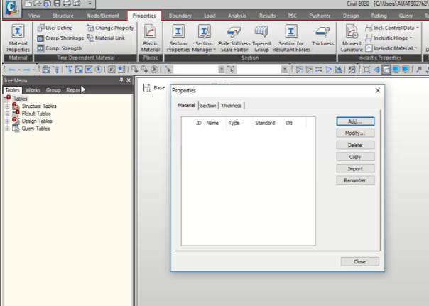
1) Define Sections and Materials
Section shapes and Materials can be pre-defined via the Properties Tab.
2) Production of the Structural Model
Aside from manually creating the structural model, various wizards are available for creating both longitudinal and transverse models for PSC Segmental Bridges. These are accessed via the Structure Tab.
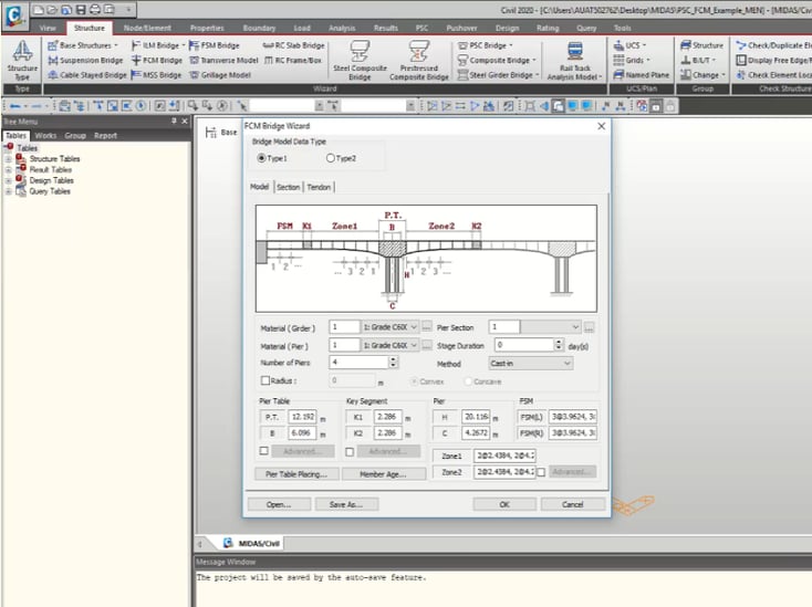 Figure 11. MIDAS CIVIL Structure Wizards
3) Checking Construction Stages
Accurate construction stages will need to be defined for the structural model. The definition of the construction stages can be accessed in multiple ways:
· By going to the Load Tab -> Construction Stage -> Define C.S.
· By right-clicking on the specific stage in the Tree Menu
· By clicking on the Define C.S. button at the top-left of the model view.
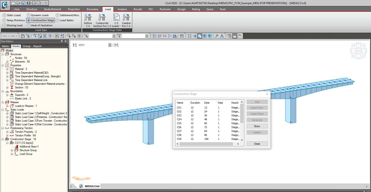 Figure 12. Checking Construction Stages
4) Adding Other Loads
The wizard may have missed some static/construction loads relevant to the users' project, which the user will need to add manually. Additionally, live loads and seismic loads should also be manually added.
5) Analyze, Perform Design, and Export Report
After analysis of the model is carried out and load combinations are defined via the Results Tab, PSC Design can then be done via the PSC Tab. Results can then be exported in an Excel File via the Excel Report button.
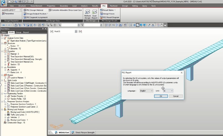 Figure 13. Design and Report Export via PSC Tab
References
1. Association of State Highway Officials (AASHTO) LRFD Bridge Design Specifications
2. US Department of Transportation Federal Highway Administration. “Post-Tensioned Box Girder Design Manual”.
3. Theryo, Teddy S. “Segmental Concrete Bridges”. Bridge Engineering Handbook: Superstructure Design (2nd ed.), edited by W. Chen et al., CRC Press, 2014, pp. 91-170.
4. Sauvageot, G. “Segmental Concrete Bridges.” Bridge Engineering Handbook, edited by Wai-Fah Chen and Lian Duan, 2000.
5. Rathod, Piyush & Pitroda, Dr. Jayeshkumar & Bhavsar, Jaydev. (2015). A SHORT STUDY ON LAUNCHING TECHNIQUES.
6. Muñoz-Rojas et al. (2015). AN INNOVATIVE SYSTEM OF PRECAST SEGMENTAL SPAN-BY-SPAN CONSTRUCTION FOR SPAN LEGNTHS OF ABOVE 100 m.
7. Hamad El Hamad, Furkan Tanhan, (2018). ANALYSIS OF POST-TENSIONED CONCRETE BOX-GIRDER BRIDGES.
8. Florida DOT. “Grouting of Bridge Post-Tensioning Tendons Training Manual”.
Watch the Full Webinar Video


/Construction%20analaysis%20of%20precast%20bridge/Construction%20Analysis%20of%20Precast%20Bridge%20original%20345%20240.png)
/345%20240/Structural%20analysis%20of%20Incrementally%20Launched%20bridge.png)