 Get Started midas Civil
 Featured blog of this week

Please fill out the Download Section (Click here) below the Comment Section to download the FULL PDF File.
Table of Contents
*Click the content to move to the section
- Why Cables?
- Example
1. Introduction
It’s so surprising to comprehend that the cables can withhold dead and live load of bridges which spans even up to 1000m. This quality of cable-stayed bridges makes them more captivating and challenging at the same time for engineers. Cable-stayed bridges comprise cables, girders and pylons. Today we’ll have a quick walkthrough about the cable forces of the bridge.
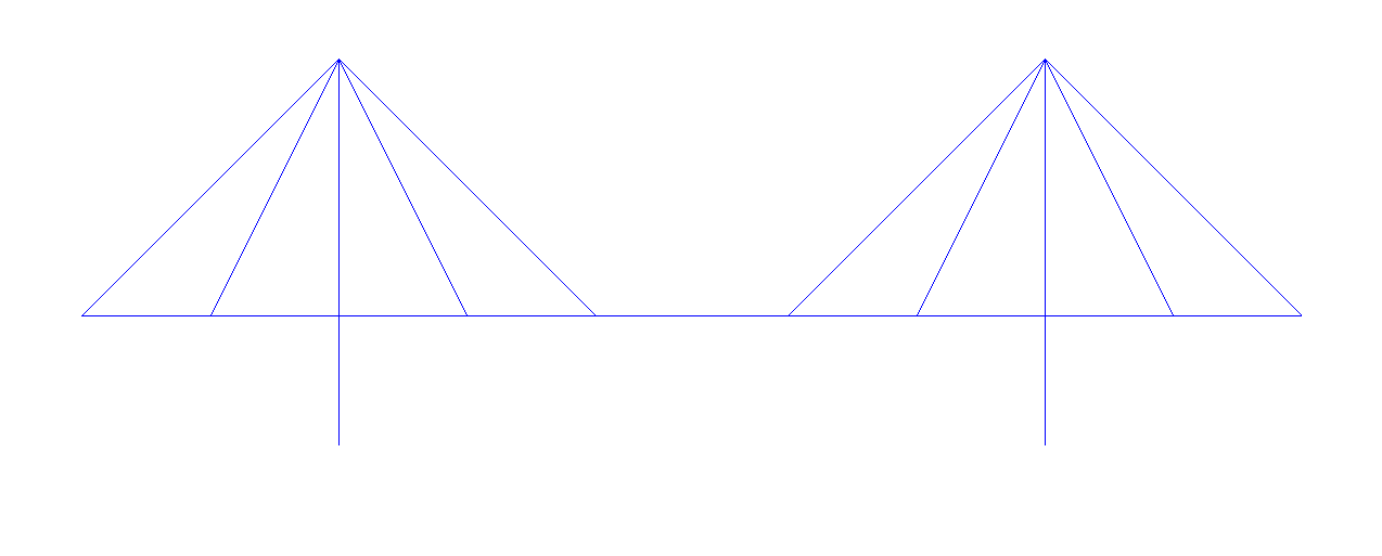 Figure 1. Cable Stayed Bridge
Why Cables?
So firstly, we’ll start by, why cables? Cables cannot take bending moments but can withstand high axial forces. But why can’t a cable take a bending moment? What’s the difference between a simple rod and a cable?
A cable consists of numerous strands whereas a rod has a solid cross-section. Due to these small dia strands, the moment of inertia of a cable reduces drastically thus reducing the bending capacity. But, this comes with a trade-off. We often get the strength of the rod in the range of 500 - 600 Mpa. But due to the strain hardening phenomenon of steel, the strength of cables can be obtained as high as 1800-2000 Mpa which allows us to use cable elements to withstand huge axial forces.
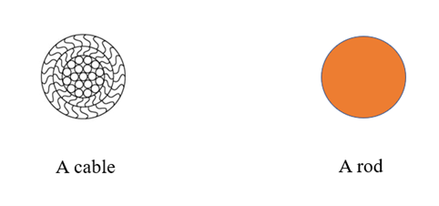 Figure 2. Cable vs Rod
We basically induce pretension in the cables, which reduces the moments in the girders. Less moment means lighter girders, therefore reducing the self-weight of the structure. Seems like an interesting concept, right? But, calculating the pretension can be a bit knotty. Don’t worry! We’ll just discuss two topics - ULF (unknown load factor) and Cable Tuning and everything will be clear.
2. Unknown Load Factor
The ‘Unknown Load Factor’ function in Midas Civil calculates the initial pretension (initial cable force) that needs to be applied to the cables. In order to obtain that we need to provide the software with certain constraints according to which objective functions will be generated inside the software and the most optimal solution will be provided.
The constraints can be in the form of the bending moment of the deck or the deflection of the top of the pylon or the cable forces. The constraint can be anything.
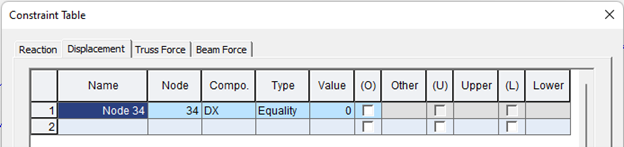
It is recommended to provide negligible displacement for the top node of the pylon. If not done, in order to satisfy the other constraints the software may provide a solution which involves high deflection of the pylon.
Now the software will provide the values of pretension forces which will satisfy the given constraints.
3. Cable Tuning
Since ULF is an iterative process, we cannot get the desired initial pretension in one go.
Here comes the concept of cable force tuning.
We can fine-tune the pretension force using the influence matrix in order to get the initial pretension that produces the desired bending moments and deformations. ‘Cable Force Tuning’ allows the user to adjust the cable force and to check the displacements of the girders or the pylon in real-time, without reanalyzing the structure.
Let’s take a small example to understand this concept.
Example
Step-1:
So, we’ve modelled a simple 3-span fanned cable-stayed bridge with 8 cables and cable pretension as unity.
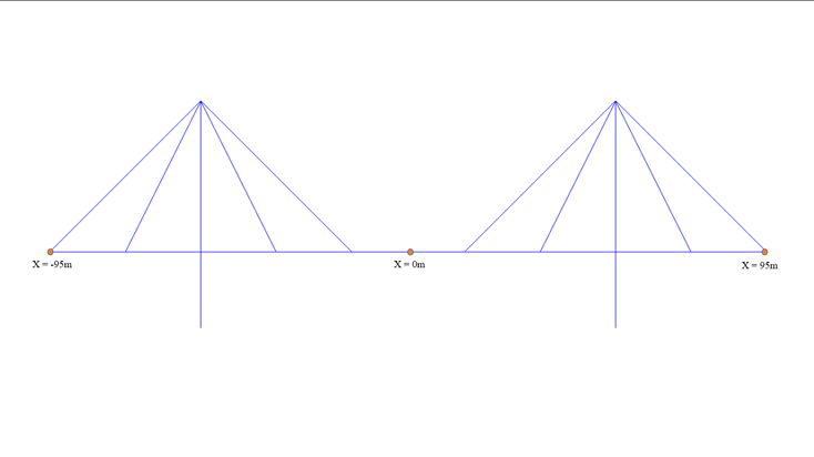 Figure 3. 3-span fanned cable stayed bridge
Step-2:
Now I want to know what should be the pretension in cables in the completed state of the bridge.
So now I’ll use “Unknown Load Factor” method. I’ll instruct the software with some constraints - Here for example we have used the bending moment of the deck (elements 5,6,8) and the deflection of the top node (node no. 34) of the pylon as constraints
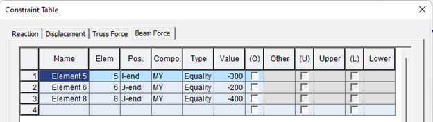
The software will make the objective functions and will provide us with certain pretension values for the cables. Here, 333, 254, 193 and 340 tonf respectively for the four cables.
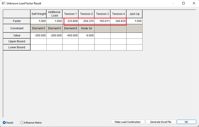 Figure 4,5,6 - example for Cable Tuning
We can observe from the results that the bending moment in the deck reduces to a great extent when we apply the obtained pretension in the cable. Also, the bending moment in the pylon becomes almost negligible thus we need to design it for axial forces only.
.png?width=734&height=413&name=BENDING%20MOMENT%20WITH%20ulf%20PRETENTION%20IN%20CABLES%20(1).png)
.png?width=734&height=414&name=BENDING%20MOMENT%20WITH%20ulf%20PRETENTION%20IN%20CABLES%20(2).png)
Step-3:
Now we are ready to have hands-on cable tuning. Let’s dive into the most interesting part.
We got the pretension values from the ULF method. Right? But we want to change the forces as per our requirement.
This is what the interface of cable tuning looks like.
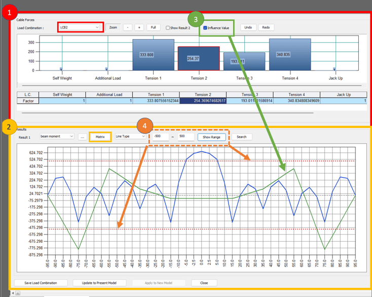 Figure 9 - Interface of Cable Tuning
So let’s understand this interface here.
1. Top bar graph: Pretension values of the cables which we obtained from the ULF method
2. Bottom line graph: Blue line shows the variation of bending moment along the length of the bridge due to the combination of all the loads. (LCB2)
3. Influence Value: Green line in the bottom graph is the influence line for the “Tension 2” pretension. Every force will have a different influence line diagram. The influence line represents how the pretension force in cable-2 will affect the final result (bending moment in this case).
4. Range: Dotted Red line in the bottom graph represents the range of bending moment between which we want our blue line to be. (let’s say 500 tonf.m in this case)
Now, as a designer, let’s say I want the bending moment should be under 500tonfm and I could observe that it exceeds at around x=0 (mid of the bridge). So we want to change the cable forces to achieve this. How do we decide whether we want to reduce or increase the force and in which cable?
Don’t worry, the influence matrix is here. The “Matrix” option here will do our job.
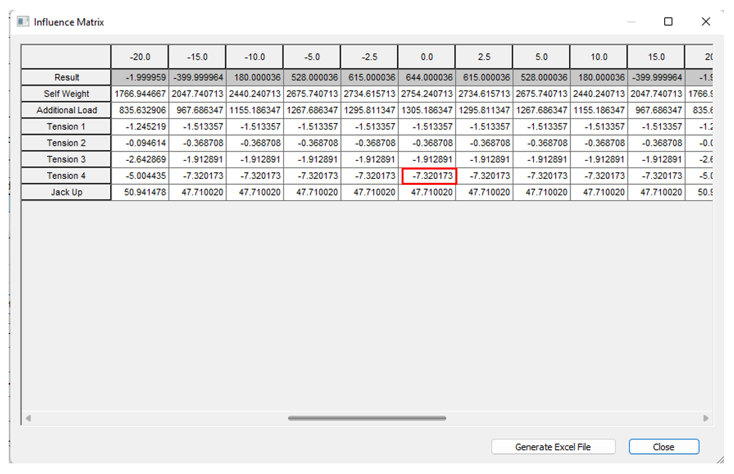 Figure 10. Influence Matrix
Here we will see the column with x=0. We can observe that magnitude of tension 4 (cable-4) is the highest among the pretension loads. The negative sign represents that it will have an invert effect on the result i.e. when we increase the “Tension 4” pretension, the bending moment will decrease and vice versa.
So to decrease the moment at x=0, we will increase the pretension for cable-4. Let's say we increase the “Tension-4” to 360 tonf from 340.83 tonf.
.png?width=734&height=425&name=influence%20matrix%20(2).png) Figure 11. Influence Matrix (2)
Figure 11. Influence Matrix (2)
We can now observe that the moment (blue line) is almost under control now at x=0. We can perform a few trials and errors to achieve the desired result.
We can use cable tuning while rounding off the cable forces. For example, we won’t be using 333.80 tonf pretension in an actual project. We would round it off to let's say 340 tonf so we can use cable tuning to check the behaviour of the structure and whether the rounded-off values produce results which are under the range or not.
4. Summary
For a completed state analysis of a cable-stayed bridge, we would first perform ULF to get the cable forces. This will help in reducing the bending moments in the girder and the pylon. Then we will further fine-tune the cables using the influence matrix to get the desired results.
👉Please fill out the Download Section (Click here) below the Comment Section to download the Full PDF File.


/Static%20Analysis%20of%20Cable-Stayed%20Bridges/Static%20Analysis%20of%20Cable-Stayed%20Bridges%20345%20240.png)