Get Started midas Civil
 Featured blog of this week

Please fill out the Download Section (Click here) below the Comment Section to download the Full Webinar PDF File.
This case study covers the following aspects:
*Click the content to move to the section
2. Footbridge Design Specifications and Challenges
4. Case Study - Warren Truss Footbridge
1.Introduction
A footbridge or a pedestrian bridge has mainly a purpose that allows people to walk over the bridge. The aesthetic considering harmony with the surrounding environment is an important factor in this type of bridge. Since that, the shape of the bridge is getting slender and aesthetic. And also the footbridge generally has a narrow carriageway and lightweight itself. Those characteristics make a high possibility happen the vibration on the bridge. Especially, if the frequency of walking is equal to the natural frequency of the bridge, it makes resonance phenomena. This resonance phenomenon causes a higher amplitude of vibration, which can influence the safety of pedestrians.
2. Footbridge Design Specifics and Challenges
Let’s have a look at what makes footbridge design different from a road and rail bridge and what challenges the designer might have to face when designing a footbridge. In footbridge design, aesthetics and structure robustness could be one of the key points. At the same time, the designer needs to pay attention to the stability and the vibration of the bridge. It doesn’t mean unique to footbridges but those specific points can be encountered frequently when designers design a footbridge.
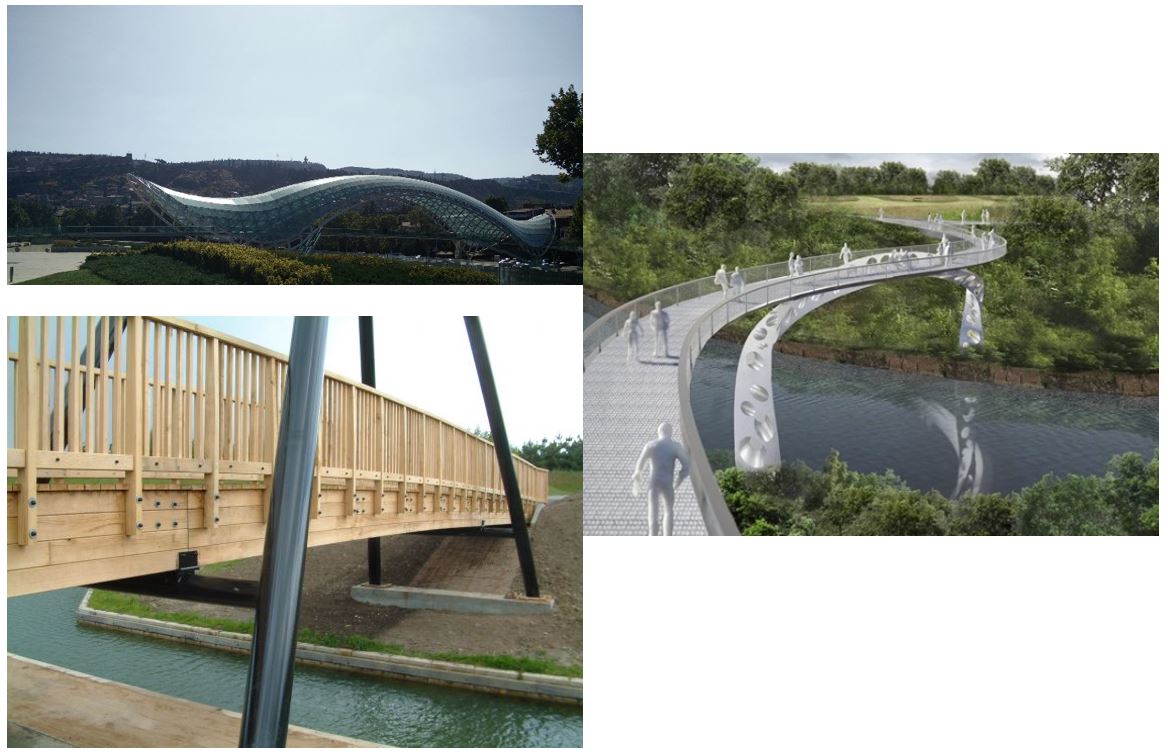
The aesthetic structure design of the footbridge is quite often developed in close cooperation with an architect. Architects have their ideas about the appearance and the visual impact of the bridge. Therefore, the shape of bridges might involve unusual or complicated geometry. The footbridge design allows for various selections of materials, so designers need to understand the properties and behavior of materials such as timber, aluminum, or glass.
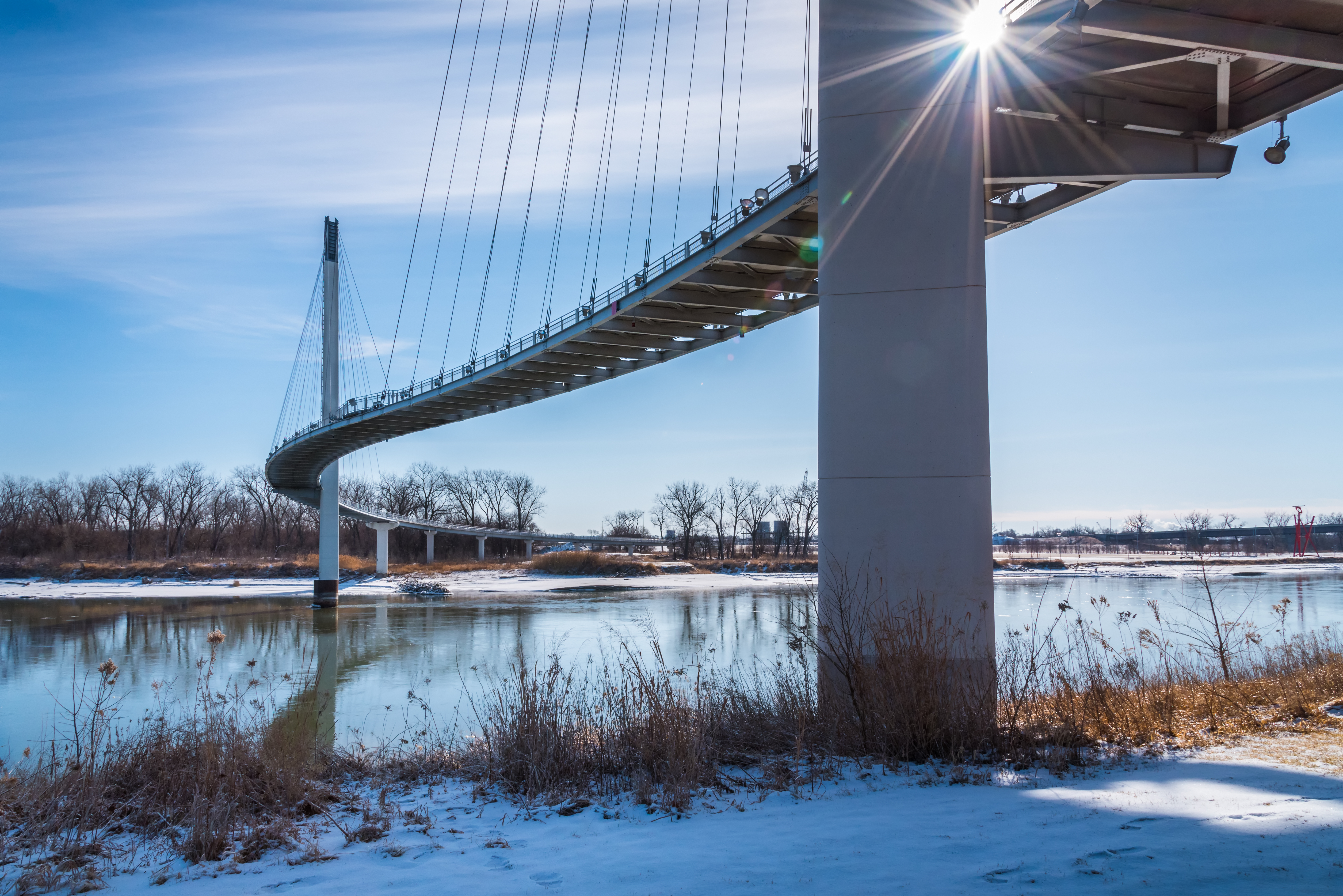
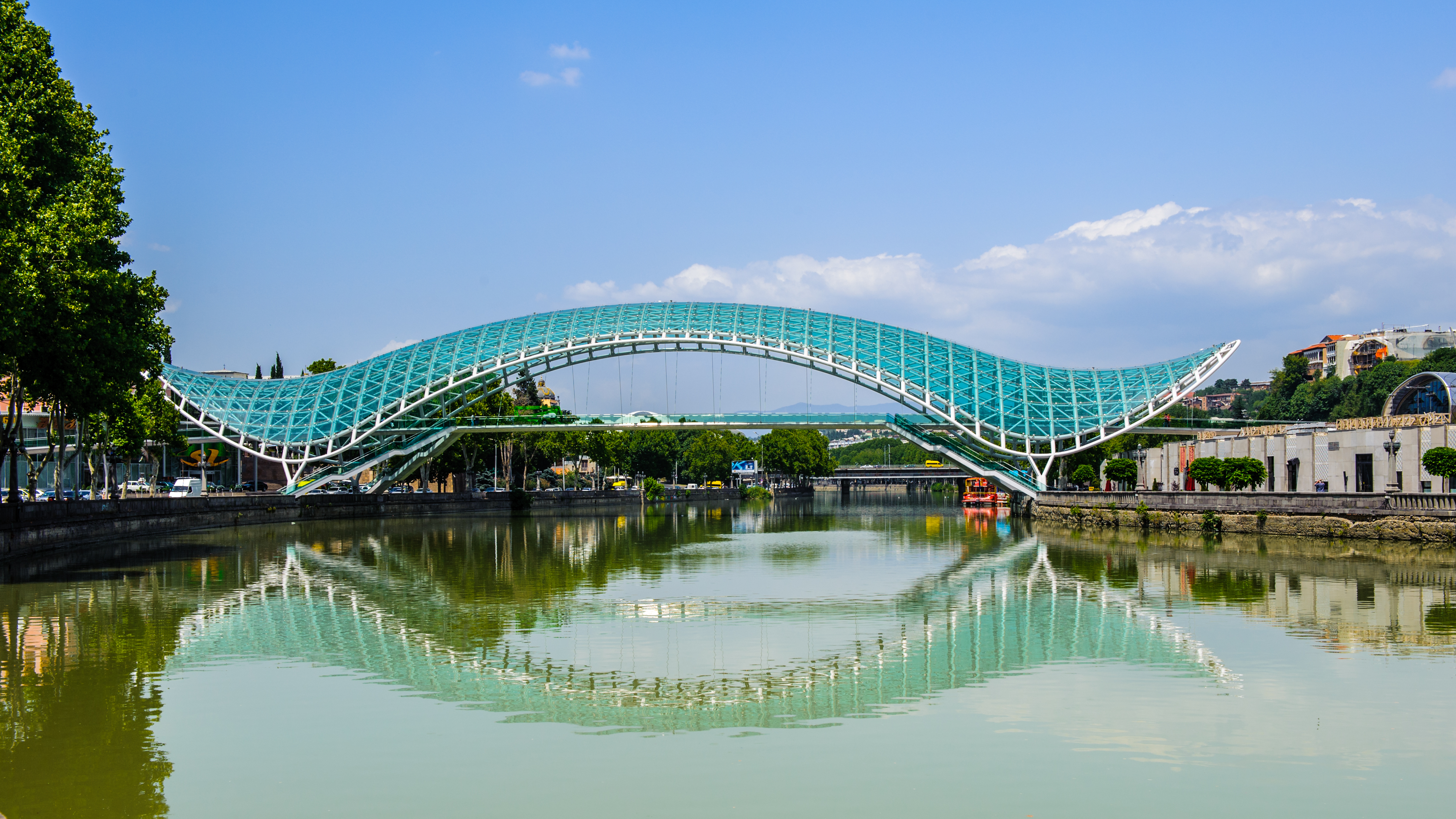
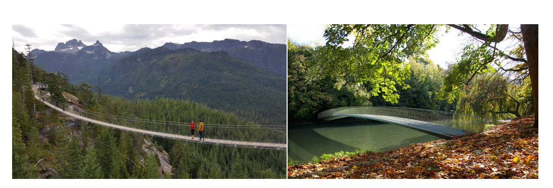 Figure 4: Slender airy footbridges
In terms of structure robustness, when designers design footbridges, probably they want a footbridge to be lightweight. So, a footbridge is often designed as a slender airy structure. At the same time, we have to ensure that they have sufficient stiffness and strength to maintain their stability including wind effects and accidental situations. Therefore, a critical load combination may be different from those common at road bridges.
The stability is also related to dynamic response and vibration. It is not the main issue for a majority of short and medium-span road bridges, but it is an important factor in the design of footbridges. If the structure has a low natural frequency, it might lead to unstable lateral response and loss of stability. Also, it might lead to vibration which may cause discomfort to users.
3. Footbridge Design Specifications and Challenges
The Eurocode proposes various requirements regarding footbridge design. Requirements for the footbridge design can be found in:
- Loading Requirements
- EN 1991-2:2003, Section 5
- EN 1991-1-4, Section 8.2
- EN 1991-1-7, Section 4.3
- Structural Design
- EN 1992 (Concrete)
- EN 1993 (Steel)
- EN 1994 (Composite)
- EN 1996 (Timber)
Footbridges are subjected to different types of live loads. The same limit state principles apply to footbridges.
Static load models for the footbridges are made up of four elementary components called uniformly distributed load, concentrated load, service vehicle, and horizontal forces. These loads are combined into groups of loads. It is a similar concept as with road traffic.
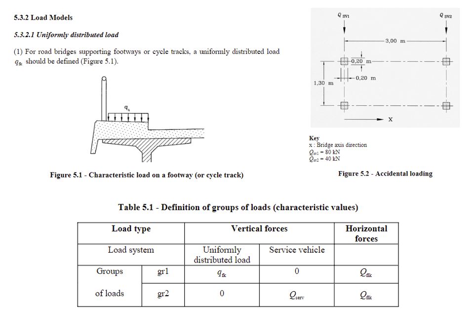
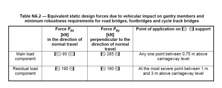
The accidental loads are covered partially in the traffic loading code, EN 1991-2 and it also covered partially in the accidental actions, EN 1991-1-7. Since accidental loads can have fatal consequences, and strengthening the structure to resist them would be uneconomical so we need to take measures to avoid them. Therefore, collision forces on piers of footbridges are reduced because the piers are usually protected by barriers. Collision forces on the deck can be avoided through this accident load if we provide sufficient clearance which is in the UK and Ireland 5.7 meters. Furthermore, for the accidental presence of a vehicle on the bridge can be avoided if a permanent barrier is installed which prevents access of vehicles on the bridge.
Dynamic Loads can be found in section 5.7, EN 1991-2. Now, we will look at what differentiates footbridges from normal road bridges of short and medium span bridge that have the application of dynamic loads. There are two key points which we need to pay attention to:
The first key point is the natural frequency of the structure. Because if any of the natural frequencies are identical to the frequency due to dynamic forces applied to the structure, there is a risk of resonance which may lead to unacceptable vibration or even loss of stability.
The second key point is to pay attention to vibrations. The vibration from normal pedestrian traffic should not cause discomfort to users so that is why the code specifies a limit defined as an acceleration limit. Dynamic effects of walking pedestrians can be represented by a periodic force, and this force will have a typical frequency of between one and three hertz. In the horizontal direction, the effects of walking pedestrians would have a frequency between 0.5 and 1.5 hertz, and if there’s a group of joggers crossing the bridge, that may induce forces with a frequency of about three hertz; so we can see that this range says from 0.5 to 3 hertz would be a critical spectrum. Furthermore, if any of the natural frequencies of the structure is within this spectrum, there is a risk of issues related to the vibration or stability so specific models and detailed criteria on how to fulfill it and how to achieve that the structure is stable. They are defined in a nation annex or other national application document.
/Contents/Case%20Study/new%20image%20Design%20of%20Warren%20Truss%20Steel%20Footbridge/Equivalent%20static%20design%20force%20due%20to%20the%20impact.png?width=734&name=Equivalent%20static%20design%20force%20due%20to%20the%20impact.png)
For the UK and Ireland, Eurocode 1 specifies the maximum vertical deck acceleration which has a limiting serviceability value in the range between 0.5 and 2 m/s2. The exact limit value is calculated based on a formula in the code and it depends on the site usage route redundancy and structure height. Single pedestrian or a pedestrian group load is represented by the application of vertical pulsating force which moves across the span of the bridge. The pulsating force can be calculated via the formula shown in figure 7. The formula has various parameters.
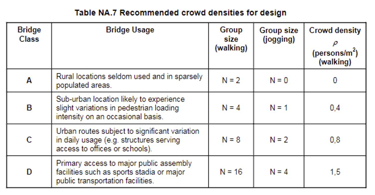
The footbridges for the purpose of dynamic loading are split into four classes depending on the location and usage. The dynamic force is applied, and also we should know that the pedestrian speed crossing. It is also defined which helps us to define the duration of dynamic loading.
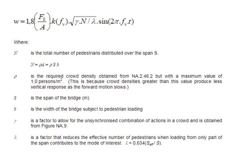
The other aspect of dynamic loading would be loading crowded conditions so if a bridge is located in the city center or close to a stadium, it may get into the crowded state instead of using a point single force pulsating and moving across the bridge. The dynamic loading is modeled by a vertical pulsating distributed load.
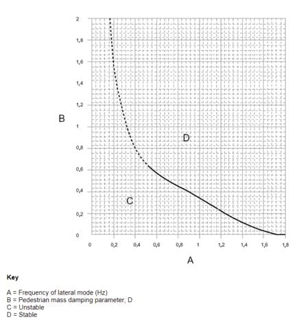
That helps us to assess the possible vibration issue and the other requirement regarding the natural frequencies. If there are no significant lateral modes with frequencies below 1.5 hertz. We may assume that the structure is stable. It means there is no risk of lateral instability. If any of the critical frequencies are lower than 1.5 hertz then there are additional checks to perform or to introduce some dumping devices or we may redesign the structure.
Apart from the dynamic effects of pedestrians, in certain situations, we may need to investigate the dynamic effects of wind loading. The Eurocode dealing with the wind loading also provides general guidance. It says that dynamic magnification effects due to vertical response can be ignored if fundamental frequencies in bending and torsion are greater than 1 hertz or we may need to fulfill alternative conditions, taking into account that generally we want to avoid frequencies below 1.5 or even 3 hertz. It means that for most bridges where we fulfill the condition for the pedestrian dynamic load. We are fulfilling the condition for the wind loading as well. But for the long span or special structures, it is something which needs to be taken into account.
4. Case Study – Warren Truss Footbridge
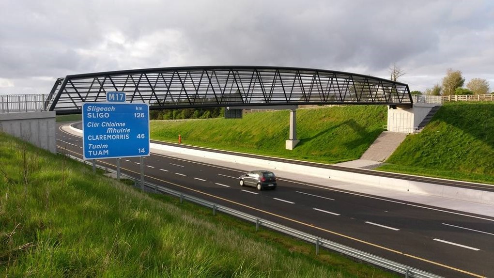 Figure 11: Warren truss footbridge
The bridge of the case study has a span of 50 meters, a clear internal width of 3 meters, and a maximum structure depth in the mid-span of 4.2 meters. Both top and bottom chords of the truss are curved in the gentle radius to improve the appearance although in this particular case the aesthetics weren’t the governing factor for the design because of the rural location of the bridge with a low flow of pedestrians. The design of this footbridge was actually developed as a result of a value engineering exercise or a value engineering proposal because the original structure was a two spans slab beam bridge. We proposed a single-span structure to avoid placing support in the center median of the motorway.
And the truss works well for this arrangement. We can focus on how this particle structure or generally truss can be generated in midas Civil. How we can generate a model in relation to what we discussed in the Eurocode requirements for dynamic response and natural frequencies. We will look into stability and dynamic response and again how this can be performed in midas Civil. Then global static analysis member verification and the generation of the design report.
4.1 Model generation – Geometry
A model can be defined by using functions related to modeling manually. midas Civil provides various options to model. The user can use the ‘Truss Wizard’ function to model truss shape elements directly. If there is a CAD file, it can be imported to midas Civil.
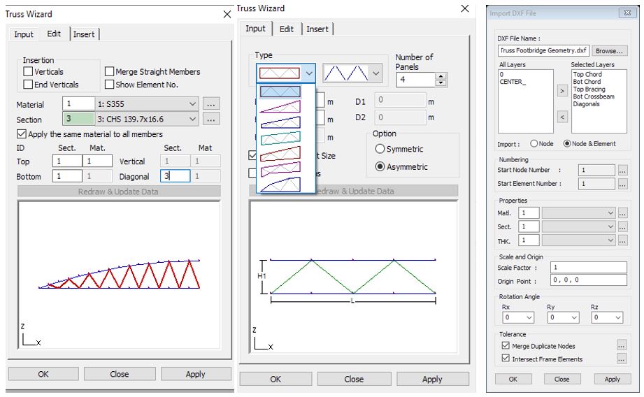 Figure 12: Truss Wizard function and CAD import
4.2 Model generation – Structure’s properties
The member sections and material properties are selected in the database of midas Civil. The user doesn’t need to define additional properties if there is desired property in the database. The bearings of the bridge are modeled via the Elastic Links function.
/Contents/Case%20Study/new%20image%20Design%20of%20Warren%20Truss%20Steel%20Footbridge/2.png?width=604&name=2.png) Figure 13: Structure’s properties
Figure 13: Structure’s properties
In the bridge model, dummy beam elements are created to apply pedestrian dynamic loads. In order to perform the dynamic analysis in midas Civil, the user needs to set some options regarding the mass of a structure. Those options are called ‘Convert Self-weight into Masses’ and ‘Loads to Masses’.
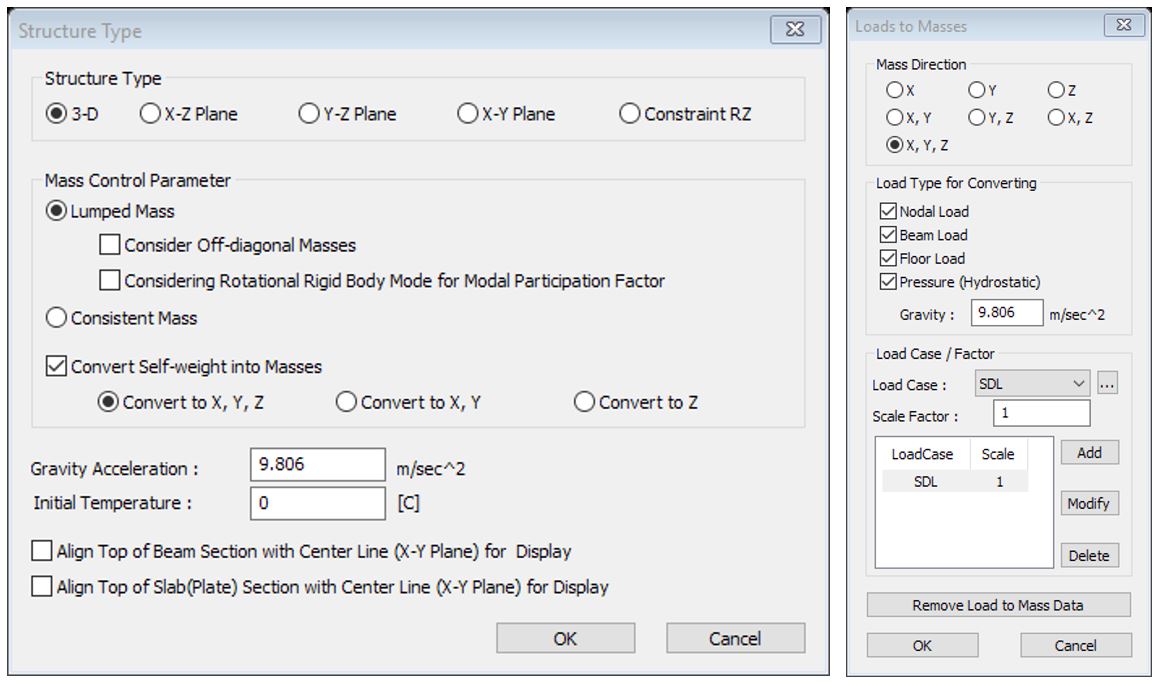 Figure 14: Structure type and Loads to Masses functions
4.3 Stability and Dynamic Response
There are two key parts. One is the analysis to obtain a natural frequency and the other is the dynamic analysis to obtain a dynamic response. To investigate the natural frequencies of the structure in midas Civil, the user need to turn the ‘Eigenvalue Analysis Control’ function. Here, we can select the analysis type, the number of frequencies, and so on.
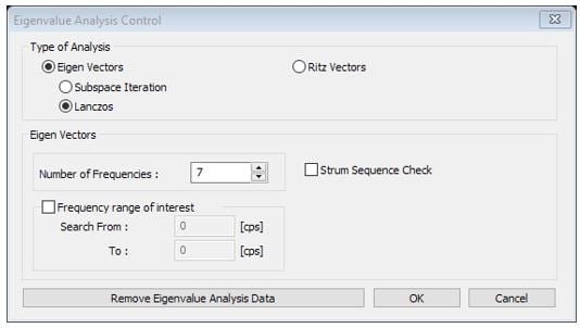 Figure 15: Eigenvalue Analysis Control function
The output from the eigenvalue analysis can be either numerical like in this example. For each mode, we can see the actual frequency. For example, the mode 1 in the figure has a frequency of 1.68 which is actually close to 1.5 hertz but we can notice that it is vibrating in the longitudinal axis of the bridge for the modal participation masses. So it is not critical. The second mode has a frequency of 2.53 hertz and it’s vibrating in the y-axis so it is a lateral transverse vibration. And the third mode has 3.47 in the z-axis so it is an actual vertical vibration.
/Contents/Case%20Study/new%20image%20Design%20of%20Warren%20Truss%20Steel%20Footbridge/Result%20table%20of%20the%20eigenvalue%20analysis.png?width=734&name=Result%20table%20of%20the%20eigenvalue%20analysis.png)
Figure 16: Result table of the eigenvalue analysis
For the assessment of the dynamic response, we want to prove that the vertical deck acceleration is within the limits set in the code so that any vibration is not causing any discomfort to the users. The general principles are to calculate values of pulsating force at defined time increments and to apply the force onto series of nodes along the bridge span. midas Civil provides several functions regarding the time history analysis. The procedure to apply the time history load case in midas Civil:
1. Create a time history load case.
2. Generate a time history function.
3. Apply dynamic nodal loads on the structure.
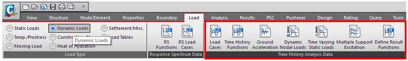 Figure 17: Time History Analysis Data
In the time history load case function, the user can specify the duration of the load, time increments, and damping. And to define a time history function, the user can input values directly. In this case, bridge designed, walking load is only applied because it’s in a rural condition and there wasn’t a requirement for joggers. If we have a structure in an urban environment or a specific requirement, we might need to define two load functions for walking and jogging.
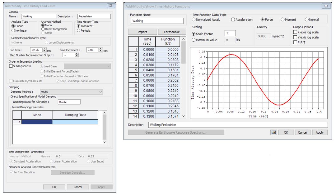
Figure 18: Time History Load Case and Functions
And then, this pulsating force defined in the time history function is applied to selected nodes on the structures via the Dynamic Nodal Loads function.
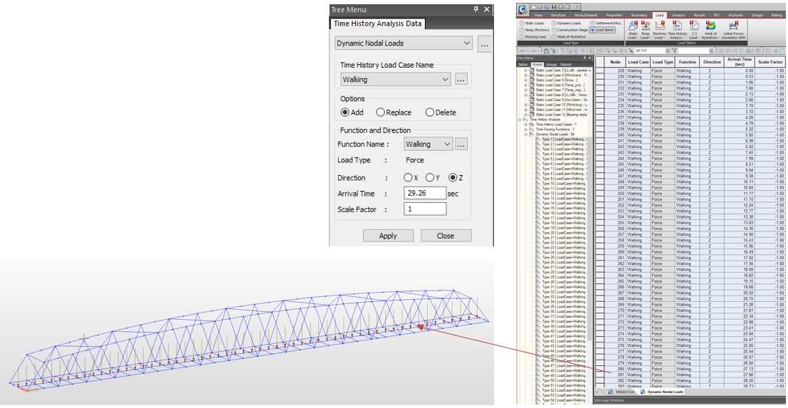 Figure 19: Time History Load Case and Functions
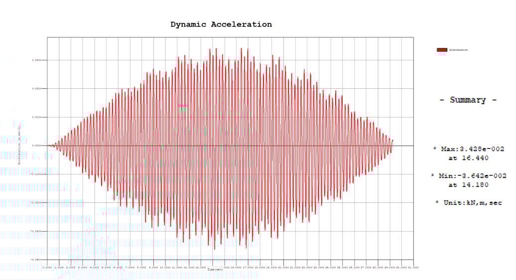
After the analysis, we can review the acceleration, forces, or displacements at any point in graphical form or numerical form. But the problem is if our time increments are hundreds per second. It means a lot of numbers to review. So it is not practical to look at results in this way. There is a function in midas Civil to allow the user to create an envelope of results for any selected point on the structure. The figure shows the dynamic acceleration results of the warren truss footbridge. The peak acceleration is 0.036 m/s2 is much smaller than the limiting value in the code, 0.5 m/s2. It is due to the low pedestrian loading. The peak acceleration is close to the middle of the time period. It says that the maximum acceleration would be at time 16 seconds and the minimum acceleration would be 14 seconds. It makes sense because the pedestrian is right in the middle of the bridge so it has the greatest effect on the vibration.
4.4 Global Static Analysis
The global static analysis is performed the same way as any other structure. Deformation, reactions, stress results, and force diagrams have been checked. Review of deformation is usually the first step after analysis to verify the correct behavior of the model. And we can decide whether pre-chamber is necessary or not through checking deflection from permanent loads.
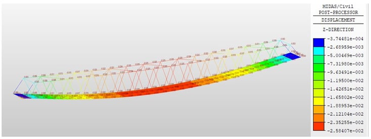
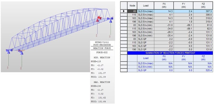
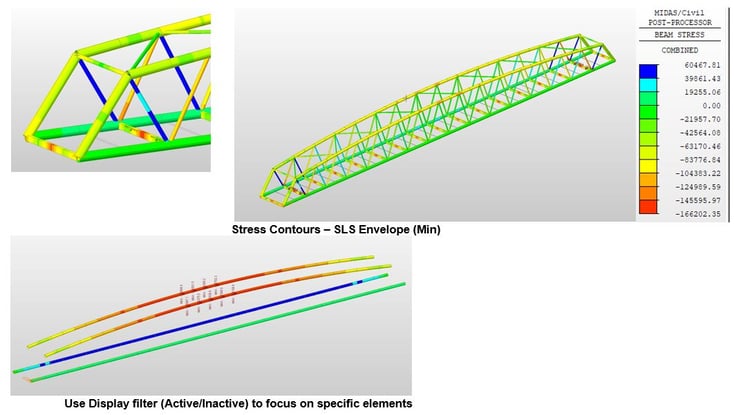
Figure 23: Member stress results
4.5 Member Verification
Member verification is defined as a set of checks and it is the most time-consuming. Even in-house prepared design spreadsheets save time but we still need to identify critical members and manually transfer results from the structural model. midas Civil has a set of member design features to simplify this task.
midas Civil provides steel design features for Eurocode 3, section 6. There are 3 ways to obtain verification results. Results table as shown figure 25 shows the design results for the selected members. These results can be checked as a graphic view or text format.
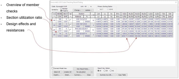
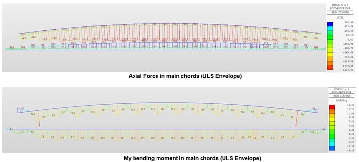
Figure 25: Member force results
/Contents/Case%20Study/new%20image%20Design%20of%20Warren%20Truss%20Steel%20Footbridge/Member%20force%20results.png?width=734&name=Member%20force%20results.png)
Figure 26: Member force results
Watch the full webinar video