Get Started midas Civil
 Featured blog of this week

Live Load Dispersion on Buried Structures Around the World
Please fill out the Download Section (Click here) below the Comment Section to download the Complete Guide to Composite Sections Guide
Table of Contents
1. What is Live Load Dispersion?
1) American Standards
2) European and British Standards
3) Australian Standards
4) Indian Standards
1. What is live load dispersion?
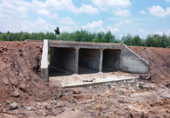
As the name suggests, the live load dispersion over buried structures is the dispersion of moving traffic loads along the thickness of earth fill above the structures. But before going ahead with the live load dispersion, one must have a basic idea of Culverts. The stiffness of the fill plays a vital role in the distribution of the loads. Thus, when traffic flows over underground structures like culverts, the loads are not applied directly over them like bridges. The earth fills above the structures help in the dispersion of the loads coming over it, thus enabling the engineers to obtain an economical design.
2. How to disperse the loads?
Researchers worldwide have coined few empirical equations since no proper mathematical calculations have been derived for calculating the dispersed loads. Thus, countries across the globe follow different sets of guidelines while designing buried structures.
This article will discuss the standards followed in America, Europe, Britain, India, and Australia, thus covering the norms followed from one corner of the world to another.
- American Standards
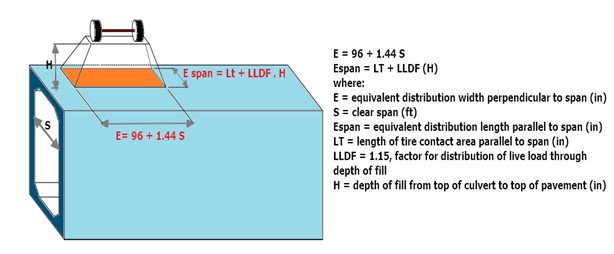
The live load dispersion on buried structures (box culverts) is calculated in accordance with AASHTO LRFD, clause 3.6.1.2.2. The design live loads applied to the top slabs of box culverts include the HL-93 truck and tandem loads for box culverts of any span length. The fill depth is measured from the top of the roadway to the top of the top slab of the structure.
Case 1: When the depth of fill is less than 2 feet
The truck axle loads are uniformly distributed over a rectangular area with dimensions, as shown in the figure.
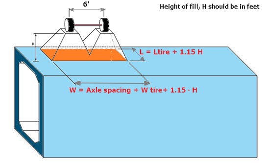
Case 2: When the depth of fill is greater than 2 feet.
When the depth of fill exceeds 2 feet, wheel loads are considered to be uniformly distributed over a rectangular area with sides equal to the dimension of the tire contact area and increased by either 1.15 times the depth of the fill in select granular backfill or the depth of the fill in all other cases. As the depth of the fill increases, the dispersion area overlaps. The total load will be uniformly distributed to the entire area in those scenarios.
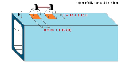
Figure 2: Wheel load dispersion; hc > 2 ft - Source: AASHTO LRFD
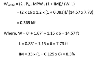
Other design considerations concerning the depth of fill for the calculation of live load dispersion are MPF (Multiple Presence Factor) and IM (Dynamic Load Allowance). Based on extensive trials, multiple loaded lanes are not considered in culvert design. MPF of 1.2 is considered for a single-loaded lane. Dynamic Load Allowance (IM) for culverts shall be considered when the depth of fill over the culvert is less than 8ft. The equation to calculate the dynamic load allowance is as follows:
𝐼𝑀 = 33 ∙ (1.0 − 0.125 ∙ 𝐷𝐸) ≥ 0%
Where: 𝐷𝐸= the minimum depth of earth fills above the structure (ft)
Example: Over a fill depth of 6 feet, a single HL-93 truck axle configuration produces a live load intensity of:
- European and British Standards
According to clause 4.3.6 in BS EN 1991-2:2003, the wheel loads (Model 1 and Model 2) are dispersed along the fill depth at an angle of 45o. Even though the European and British standards suggest a load dispersion of 1:1, traffic loadings have a worse effect on fill depths of between 0.6m and about 1m than those on a depth of 0.6m.
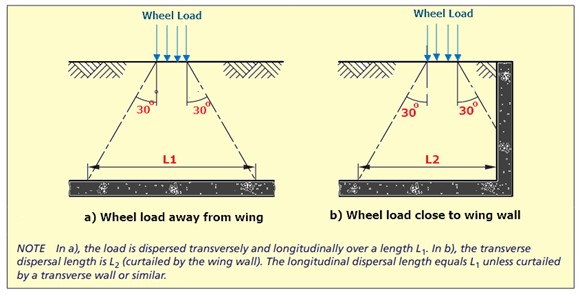
Thus, engineers follow PD 6694-1-2011, according to which a wheel load or other vertical load may be dispersed transversely and longitudinally through the fill at an angle of 30° to the vertical, as shown in Figure 10(a). When the dispersal zone of a traffic load is curtailed by a wing wall or similar, the wheel load is transversely dispersed over the curtailed dispersal zone, as shown in Figure 10(b)
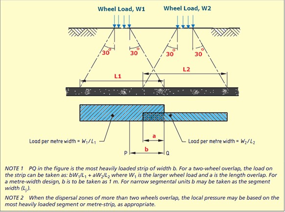
When the dispersion zones of different wheels overlap, the following guidelines should be followed:
- For in-situ structures analyzed using the three-dimensional model, the dispersed patch loads should be superimposed.
- When the in-situ structures are analyzed using a two-dimensional or a meter strip model, the load per meter width in the transverse direction may be based on the total load on the most heavily loaded meter strip as shown in Figure 11.
Braking and acceleration forces: PD 6694: Clause 10.2.8.2 - For buried structures with less than 0.6 m depth of earth cover (Hc), the full value of the braking or acceleration action described in BS EN 1991-2:2003, 4.4.1, should be applied.
- Australian Standards
Traffic load dispersion on buried structures is calculated following the code AS 5100.2, Table 14.3. The values of unfactored vertical pressure at corresponding depths are tabulated for 300LA Train load. Like the Euro and BS standards, Vertical force is calculated assuming 1 to 2 longitudinal and transverse distributions, max width of 4.5 m.
- Indian Standards
The wheel load dispersion over culverts is calculated following IRC 112, Informative annexure B-3, the effect of live loads on the deck slab. The distribution of loads through fills and wearing coats shall be assumed at 45°, along and perpendicular to the span.
IRC 112-B3.3: The effect of contact of the wheel or track load in the direction of span length shall be taken as equal to the dimension of the tire contact area over the wearing surface of the slab in the direction of the span plus twice the overall depth of the slab inclusive of the thickness of the wearing surface.
The dispersion width perpendicular to the traffic direction is taken as the effective width of the slab. IRC 112-B3.3: For a solid slab spanning in one direction, the effective width, beff = α.a (1- a/lo) + b1
Where l o = effective span of the culvert
a = distance between the center of gravity of the concentrated load and the nearest support
b1 = the breadth of concentration area of the load, i.e., the dimension of the tire or track contact area over the road surface of the slab in a direction at right angles to the span plus twice the thickness of the fill or surface finish above the structural slab
α = Depends upon the ratio (b / lo) where b is the width of the slab (Refer to Table 1)
Note: The effective width shall not exceed the actual width of the slab; and provided further that, when the load is near the unsupported edge of a slab, the effective width shall not exceed the above value nor half the above value plus the distance of the load from the unsupported edge.
|
b/lo |
α for simply |
α for |
|
Supported Slab |
Continuous Slab |
|
|
0.1 |
0.4 |
0.4 |
|
0.2 |
0.8 |
0.8 |
|
0.3 |
1.16 |
1.16 |
|
0.4 |
1.48 |
1.44 |
|
0.5 |
1.72 |
1.68 |
|
0.6 |
1.96 |
1.84 |
|
0.7 |
2.12 |
1.96 |
|
0.8 |
2.24 |
2.08 |
|
0.9 |
2.36 |
2.16 |
|
1 |
2.48 |
2.24 |
|
1.1 |
2.6 |
2.28 |
|
1.2 |
2.64 |
2.36 |
|
1.3 |
2.72 |
2.4 |
|
1.4 |
2.8 |
2.48 |
|
1.5 |
2.84 |
2.48 |
|
1.6 |
2.88 |
2.52 |
|
1.7 |
2.92 |
2.56 |
|
1.8 |
2.96 |
2.6 |
|
1.9 |
3 |
2.6 |
|
2 and above |
3 |
2.6 |
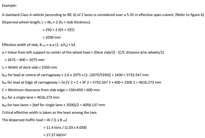
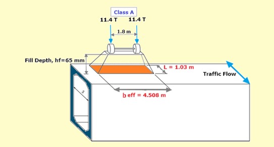 Figure 6: Live load dispersion of Class A vehicle
The above literature shows the importance of traffic load dispersion over buried structures. The economy in the design achieved is something that cannot be neglected even though the calculation of the dispersed area is tiresome and grumpy.
But don’t worry. The Vehicle Live Load Generator tool of midas Civil enables the engineers to calculate and apply the dispersed loads in the nick of time. For the time being, only Indian guidelines are included. Other code clauses worldwide will be incorporated into the tool soon.
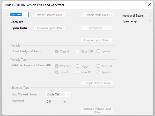
Figure 7: Vehicle Live Load Generator User Interface
4. What's next?
In this blog, we discussed the live load dispersion of traffic loads through earth fill worldwide. The upcoming blog will discuss the pros and cons of 2D and 3D culvert modeling. Stay tuned.
References:


.png)