Get Started midas Civil
 Featured blog of this week

Seismic Analysis of Underground Structures
Please fill out the Download Section (Click here) below the Comment Section to download the Complete Guide to Seismic Anlalysis
Table of Contents
2. Response Displacement Method
3. Equivalent Inertial Force Method
4. Equivalent Horizontal Acceleration Method
1. Introduction
If you are reading this, you must have heard about the seismic analysis of structures. But today we will be digging through the seismic analysis of Underground Structures. Typical underground structures includes Tunnels, Subway Stations, Underground Parking lots, Culverts, Conduits etc. These structures should be designed to not only resist the overburden loads but also the seismic load.
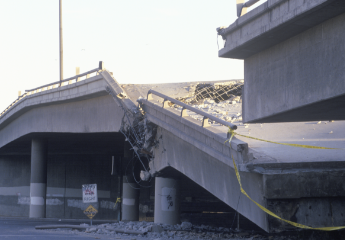
Normally, when we think about underground structures, we assume that they will not suffer any catastrophic damage from earthquakes as they are completely enclosed by soil. But this opinion has been changed due to damaging and failure of underground structures during previous earthquakes .
Underground structures typically have a high cost of construction and long-term usage hence the seismic analysis and design is crucial for minimizing risks and damage during an earthquake. The simplest approach is to ignore the interaction of the structure with soil and apply the free-field deformation to the structure but Soil-Structure interaction plays a major role. In contrast to above-ground structures where inertia forces are crucial, the deformation of the surrounding soil determines the seismic response of underground structures. Depth of structure, type of soil, relative stiffness of structure and soil, duration of earthquake etc. determines the response of structure.
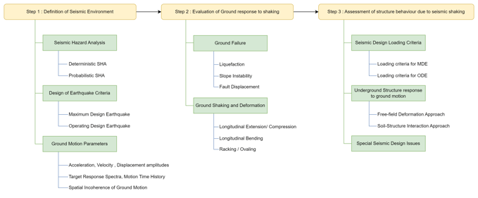
Underground Structure Seismic Analysis and Design Procedure
Today we will be going to discuss four methods frequently used for the seismic analysis of underground structures:
- Response Displacement Method
- Equivalent Inertial force method
- Equivalent Horizontal acceleration Method
- Time History Method
2. Response Displacement Method
Starting with the most used method for the analysis here. Every engineer, while studying seismic analysis must have comes across the Response Spectrum method.
The curve showing the maximum response (displacement, velocity, acceleration) versus structural frequency or time period is called the response spectrum. When the response used is displacement it is termed as Response Displacement curve and the corresponding method Response Di
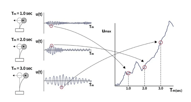
So, might be wondering how we get this curve. Assume the displacement response of three SDOF systems with constant damping ratio and different natural periods as shown in the figure above. These systems are then subjected to a seismic excitation and their maximum displacement is noted. The deformation response spectrum can be represented as a function of the natural vibration period and the maximum displacement of each ground motion system observed.
For designing an underground structure, the focus is on the deformation of the surrounding soil (free-field deformation). This is the reason that instead of going for the usual Response Acceleration method, Response deformation is used.
Due to its clear physical conception and accurate simulation of the mechanical characteristic of structures, this method is employed worldwide. The Response displacement method can truly reflect the underground structure stress characteristics.
3. Equivalent Inertial Force Method
The Equivalent Inertial Force method is based on the idea that the maximum bending moment values obtained by the two methods—dynamic time-history analysis and equivalent inertial force, are same and obtained at the same location. To achieve the same outcome as that of dynamic time-history analysis, a correction factor must be applied in order to calculate the bending moment of the remaining members as well as the axial force and shear force of all the components.
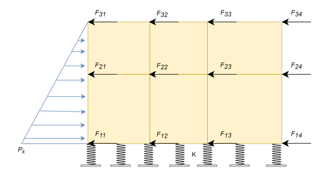
Let’s see how the equivalent horizontal seismic inertia force is obtained. In the above figure,
Where ,
F𝑖𝑗 is equivalent horizontal seismic inertia force acting on node 𝑖𝑗
𝑚𝑖𝑗 is half the sum of the mass of the member or simply nodal mass
𝑘 is equivalent inertial force coefficient.
Calculation of Equivalent Inertial Force Coefficient(k), takes the effect of :
- Depth of embedment
- Nature of Foundation Soil
- Seismic acceleration.
The Shanghai code, assumes a triangular horizontal resistance force and employs internal force correction coefficient to match the results with time-history analysis.
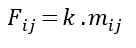
4. Equivalent Horizontal Acceleration Method
Equivalent horizontal Acceleration method is a simplified method that replaces the time-history horizontal acceleration by a static horizontal acceleration.
In this method, the basis of static acceleration distribution pattern is based on the experimental and time-history analysis results. Soft soils have an amplification effect on earthquake acceleration and velocity. The shear forces and axial forces are determined by the introduction of a correction factor, by which the results is consistent with the dynamic time history method.
In the figure above, H is the total thickness of soil, h1 depth of roof slab and h2 depth of floor slab.
β1 and β2 represents the accelerated velocity influence coefficient.
The distribution pattern of static acceleration is based on experimental studies and time-history analysis results. In a nutshell, the Equivalent horizontal acceleration method transforms the dynamic analyses into a static calculation process, so as to improve the computational efficiency.
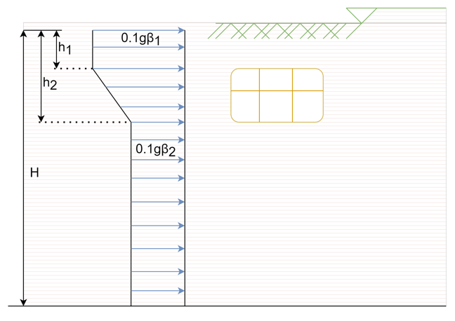
5. Time History Method

Time history analysis seeks out a solution for the dynamic equilibrium equation when a structure is subjected to dynamic loads. It calculates a series of structural responses (displacements, member forces, etc.) within a given period of time based on the dynamic characteristics of the structure under the applied loads.
The dynamic time history analysis approach employed in soft soil layer seismic response analysis of underground structures is extremely consistent with the actual scenario and calculates accurately.
This approach can also accurately reflect the interaction between the soil and the structure during an earthquake. The economy in the design achieved is something that cannot be neglected even though the calculation is complex and time taking.
6. Summary
Yeahh!! We are reaching the end of this article. Let’s go back to the beginning to summarize the things. There are two approaches to analyze the underground structures:
- Use time-history analysis on a FEM model. The complete structure including the soil is modelled and then the ground motion is applied to the boundaries. This method simulates wave propagation. A lot of calculation is needed which are too complex and makes it time-consuming.
- Pseudo-Static Approach. The aim of this approach is to convert dynamic seismic loads into equivalent static loads. This method, though has a lot of assumptions, makes designing a lot easier and faster.
Of the above discussed methods, the first three ie. Response Displacement Method, Equivalent Inertial Force method and Equivalent Horizontal Acceleration Method comes under pseudo-static approach. These methods assume soil to be linear elastic and hence are applicable to soil under small excitation.
With recent realization of their importance, countries have started developing and using specialized codes for the seismic analysis of underground structures. Some of the codal provisions are listed below:
Codal Provisions
- Guide Specifications of Design and Construction of Underground Parking Lots, Japan Roadways
- Earthquake Design Criteria for Subways, Thomas R. Kuesel , F. ASCE
- Code for Seismic Design of Subway Structures; China Architecture & Building Press
- (GB/T 51336-2018) Standard for Seismic Design of Underground Structures; China Architecture & Building Press.