Get Started midas Civil
 Featured blog of this week

Bridge Load Rating of Steel Composite Bridge as per AASHTO LRFR
Table of Contents
1. What is Bridge Load Rating?
2. What is the Process of Bridge Load Rating?
3. How to Apply Bridge Load Rating in midas Civil
4. How to Generate Results in midas Civil
1. What is Bridge Load Rating?
Bridge load rating is the measure of a bridge’s ability to carry a given live load expressed by a simple factor called the Rating Factor (RF), or referred to as Tonnage for Legal and Permit load rating. Basically, this is the assessment of bridges in their current condition to carry live loads.
Load rating is performed to assess whether the bridge needs the following:
1. Load Postings
2. Bridge Strengthening
3. Overweight Load Allowances
4. Bridge Closure

Load Rating can be performed on existing bridges if it is subjected to changes in live load, a physical condition such as loss of section due to damage, corrosion, etc., and if there are changes in the code provisions or laws.
2. What is the Process of Bridge Load Rating?
AASHTO LRFR methodology has 3 distinct levels of evaluation:
2.1 Design Load Rating – measures the performance of existing bridge to current LRFD design standards. As per AASHTO 2011 Manual for Bridge Evaluation 6A.1.5.1:
“Design Load Rating is the first-level assessment of bridges based on the HL-93 loading and LRFD design standards, using dimensions and properties of the bridge in its present as-inspected condition.”
There are two (2) levels under Design Load Rating, namely the Inventory Rating Level and the Operating Rating Level.
2.1.1. Inventory Rating Level (AASHTO 2011 MBE 6B.2.1) – This level generally corresponds to the customary design level of stresses but reflects the existing bridge and material condition with regards to deterioration and loss of section.
2.1.2. Operating Rating Level (AASHTO 2011 MBE 6B.2.2) – Load ratings based on this level generally describe the maximum permissible live load to which the structure may be subjected. - Allowing unlimited numbers of vehicles to use the bridge at the Operating level may shorten the life of the bridge.
Under Design Load Rating, the bride will be checked under HL-93 loadings, which is readily available in midas Civil (Load Tab > Moving Load > Vehicles).
2.2. Legal Load Rating – the second level of load rating that is being done to bridges that has a failing rating factor under Design Load Rating. As per AASHTO 2011 Manual for Bridge Evaluation 6A.1.5.2:
“This second level rating provides a single safe load capacity (for a given truck configuration) applicable to AASHTO and State Legal Loads. Live load factors are selected based on the truck traffic conditions at the site. Strength is the primary limit state for load rating; service limit states are selectively applied. The result of the load rating for legal loads could be used as basis for decision making related to load posting or bridge strengthening”
Various Legal Vehicle Loads will be used to check the rating factor under this level. These vehicles are also readily available in midas Civil. Below are some examples:
2.1.1. AASHTO Trucks:
 Figure 2.2 AASHTO Trucks axle configurations
2.1.2. National Rating Load
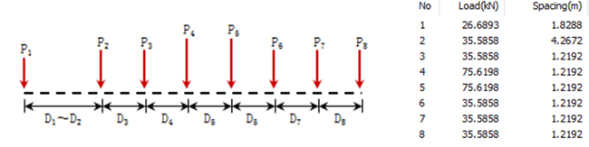 Figure 2.3 National rating load axle configuration
2.1.3. Single-Unit Bridge Posting Loads
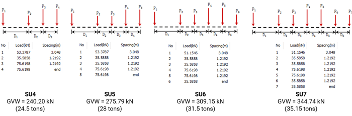 Figure 2.4 SU Vehicle loads axle configurations
2.3 Permit Load Rating – this is the last level of bridge load rating that can only be done if a bridge has a passing rating factor under design load rating and legal load rating. As per AASHTO 2011 Manual for Bridge Evaluation 6A.1.5.3:
“Permit load rating checks the safety and serviceability of bridges in the review of permit applications for the passage of vehicles above legally-established weight limitations”
Basically, the requestor of the permit will submit the axle configuration of the overweight truck. The resulting rating factor will then help you recommend if the passage of an overweight vehicle is allowed, if temporary supports are needed to be installed in the bridge to allow the passage, or if you will deny the passage.
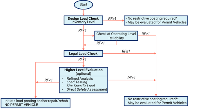
You may refer to AASHTO 2011 MBE Appendix A6A for the flowchart of these processes.
3. How to Apply Bridge Load Raing in midas Civil?
Before performing your load rating in midas Civil, the following should be done prior:
a) Complete modeling of the structure.
b) Analysis should be successfully performed.
c) Common Parameters should also be defined.
Once these are done in your model, you will now need to define the different parameters in the Rating Tab of midas Civil (Rating Tab > Bridge Rating Design). In this example, we are going to focus on the parameters under Steel Bridge Load Rating:
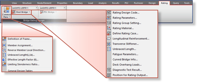 Figure 3.1 Functions for load rating parameters
3.1. Rating Design Code – for the rating design code, AASHTO-LRFR 2011 is readily available in midas Civil:
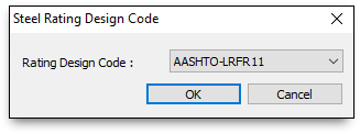 Figure 3.2 Steel rating design code
3.2. Rating Parameters – this is where you are going to set the limit states that you want to consider in your Load Rating. You can choose Strength Limit States, Service Limit States, and Fatigue Limit States.
Here, the System Factor based on AASHTO 2011 MBE Table 6A.4.2.4-1 is defined.
Under the Strength Limit States, you need to define the Resistance Factors taken as specified in AASHTO 2011 MBE Table 6A.4.2.4-1. The default values in midas Civil are already based on the code, but you still have the freedom to adjust these factors if you want to be conservative on your model.
You also have the options for Girder Type for Box/Tub Section. This will not be considered if your steel section is an I-girder.
- Single Box Section – sections are considered as a noncompact section
- Multiple Box Section – sections are considered as a compact section
- Consider St. Venant Torsion and Distortion Stresses – for Multiple Box Section, this may be neglected if relevant conditions in AASHTO LRFD Article 6.11.2.3 are satisfied. For Single Box Sections, this needs to be taken into account.
There are also optional provisions based on the code that you can consider if certain conditions are met. You may refer to AASHTO LRFD 2012 for the stated articled in each option.
If the Service Limit State option is checked, then this limit is calculated according to AASHTO 2011 MBE 6A.6.4.
- Auto-Calculation – if selected, the rating factor (RF) is calculated using the capacity calculated by the software in accordance with LRFD standards.
- User Input – if selected, the capacities are to be inputted manually (allowable compressive and tensile stresses for Design Load Rating and Legal/Permit Load Rating respectively).
For the Fatigue Limit States, if this option is checked, then it will be verified according to AAHTO 2011 MBE 6A.6.4. This limit state is only verified under Design Load Rating. Legal/Permit Load Rating is not verified under Fatigue Limit State.
- Application of Diagnostic Test Result – select if the Diagnostic Test Result is measured in terms of Stain or Displacement.
Diagnostic Test Result is then to be defined (Rating > Steel Bridge > Diagnostic Test Result).
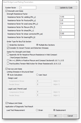 Figure 3.3 Steel bridge rating parameters dialog box
3.3. Diagnostic Test Result – this is used to consider the adjustment factor K for the comparison of measured test results with the behavior of the analytical model. Article 8.8.2.3 of AASTO 2011 MBE provides guidelines for the application of Diagnostic Test Results.
 Figure 3.4 AASHTO MBE equation 8.8.2.3-1
- User Input – when this option is selected, Adjustment Factor (K) should be inputted manually by the user.
- Auto-Calculation – when this option is selected, Adjustment Factor (K) is calculated as:
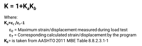
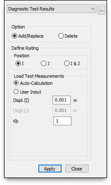 Figure 3.6 Diagnostic test result dialog box
3.4. Fatigue Parameters - Used to define parameters required for Fatigue Limit State as per Article 6.10.5.1 of AASHTO LRFD 2012
- Category – defined by AASHTO LRFD 2012 Table 6.6.1.2.3-2 based on the ‘75-yr (ADTT)SL Equivalent to Infinite Life’, Where the ‘75-yr (ADTT)SL Equivalent to Infinite Life’ is computed based on equation C6.6.1.2.3-1 of AASHTO LRFD 2012.
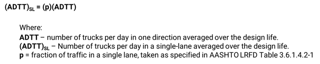
- (ADTT)SL –Single Lane Average Daily Truck Traffic defined by AASHTO LRFD 2012 3.6.1.4.2. In the absence of better information, (AADT)SL shall be taken as per AASHTO LRFD 2012 Eq. 3.6.1.4.2-1:
- n(cycles) –number of cycles per truck passage. Can be taken from AASHTO LRFD 2012 Table 6.6.1.2.5-2.
- Warping Stress Range – for the verification of fatigue, flexure stress is calculated as the summary of Longitudinal Bending Stress and Longitudinal Warping Stress.
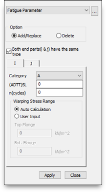 Figure 3.8 Fatigue parameter dialog box
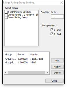
3.5 Rating Group Setting – Used to define Condition Factor on different girder groups defined on the tree menu. Condition factor can be defined based on AASHTO 2011 MBE Article 6A.4.2.3 and table 6A.4.2.3-1. Article C6A.4.2.3 is provided for the modification of these factors. Please take note that you can set different Structural Groups for your girder to assign a varying condition factor on your model.
3.6 Rating Cases – Used to defined load cases, and factors for rating. The guide is provided by AASHTO 2011 MBE Table 6A.4.2.2-1.
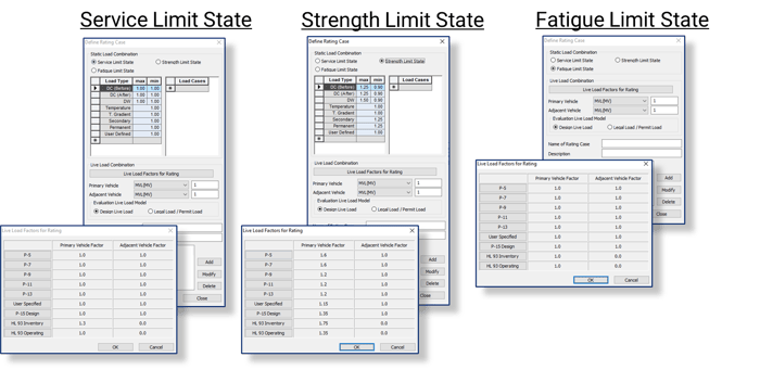 Figure 3.10 Rating cases dialog boxes for each limit states
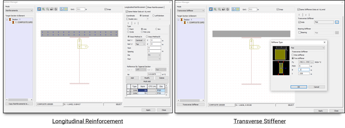
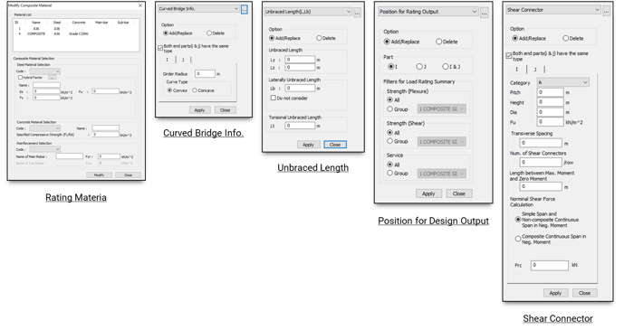
Then after setting up these code bases parameters, you also need to set up, if necessary, other parameters based on your model just like when you are doing a design in midas Civil, such as the Modify Rating Material, Longitudinal Reinforcement, Transverse Stiffeners, Unbraced Length, Shear Connector, Curved Bridge Info, and Position for Design Output.
4. How to Generate Results in midas Civil?
Once all the parameters for Bridge Load Rating are set, you can now run perform your Rating Design. Wait until your message window notifies you that your Bridge Load Rating has been performed successfully. Midas Civil will tell you the things that you need to adjust in case there are errors in your model/parameters.
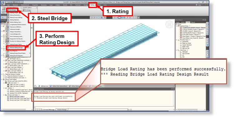 Figure 4.1 Perform rating design
Midas Civil will then calculate the rating factors based on AASHTO 2011 MBE Equation 6A.4.2.1-1. Below is the equation interpreted to Midas Civil input for reference:
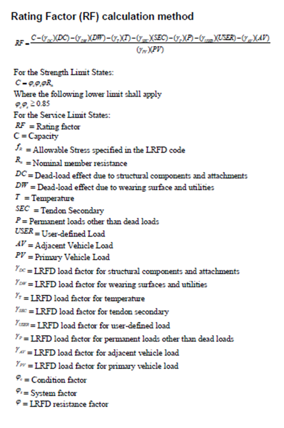 Figure 4.2 Rating factor calculation method
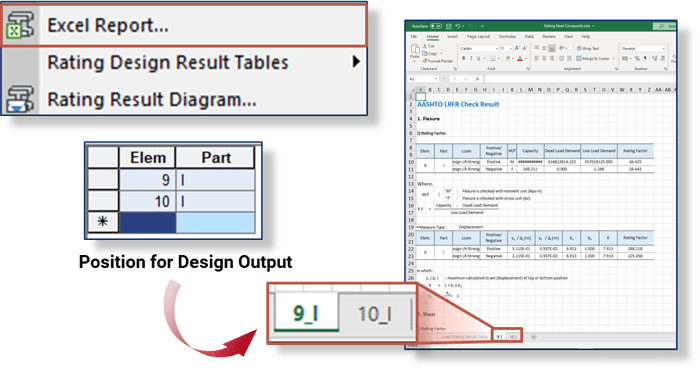
Once Rating Design is successfully performed, you can now generate different kinds of results. These results will help you in your recommendation for your bridge assessment.
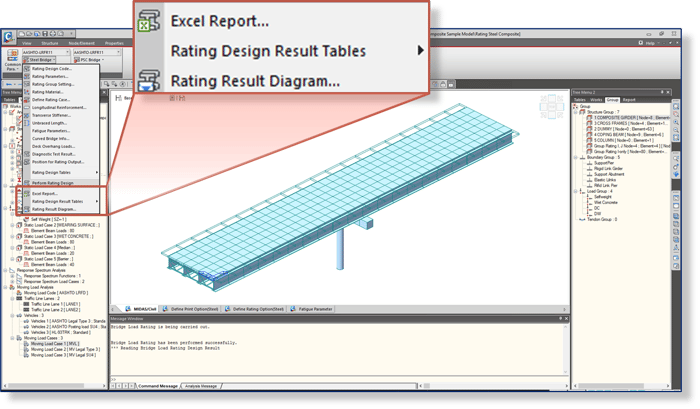
Figure 4.3. Load rating results
Please take note that for the Excel Report, detailed calculations will be generated for the elements that you set in your Position for Design Output.
Summarized tables for various rating factor result such as Service Limit State, Strength Limit State, Flexure Strength, etc., can be viewed using the Rating Design Results Tables. Below are some examples:
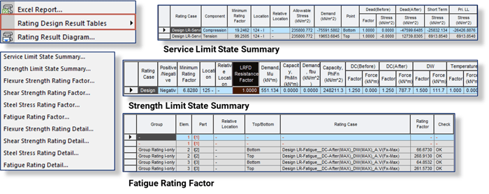
Figure 4.5 Rating design results table
You can also view graphical results for your Load Rating using the Rating Result Diagram.
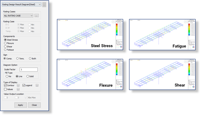
Figure 4.6 Rating results diagram
And there you have it, you just learned how to easy you can perform your load rating using midas Civil.