 Get Started midas Civil
 Featured blog of this week

The Fundamentals of midas General Section Designer
Please fill out the Download Section (Click here) below the Comment Section to download the Ebook!
Table of Contents
1. What is midas General Section Designer?
2. When to use the General Section Designer?
3. How to Navigate Through the General Section Designer
4. How to Set the Parameters for the User's Section?
5. How to Generate Results in the General Section Designer
1. What is midas General Section Designer?
Midas General Section Designer, or GSD, is a tool in midas Civil (and midas Gen) that calculates the section properties, interaction curves, moment curves, and stress distribution in general sections (sections that are not from the database).
GSD can define any irregular cross-sections and calculate their corresponding section properties. It can also generate P-M, P-My-PMz, and M-M interaction curves. Capacity design can also be performed in terms of axial forces and flexure giving you the safety ratio (demand-capacity ratio).
GSD can also generate the moment-curvature curve when nonlinearity is defined in your material, and it can also plot the stress contours for your cross-section.
2. When to Use the General Section Designer?
In midas Civil, you can easily perform your capacity design if the section of your column is defined using the common shapes in the Section Properties.
Just simply define the parameters of your column in the Column Section Data for Design or in the Column Section Data for Checking functions, and you can perform your Column Design or Column Checking to generate a comprehensive report with detailed calculates which you can use to assess your model. All these mentioned functions are in the Design Tab under RC Design.
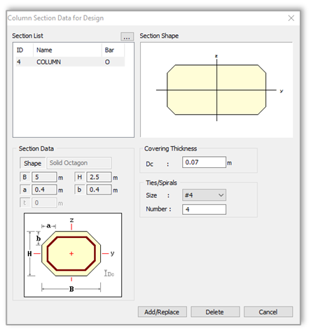 Figure 2.2 Column Section for design dialog box
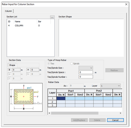
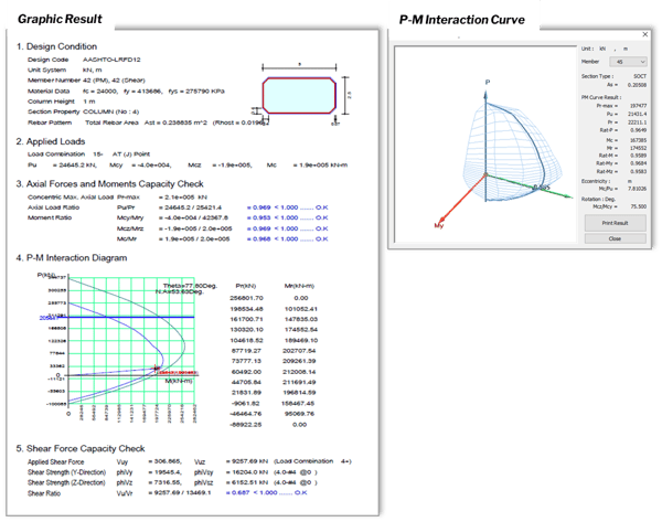 Figure 2.4 Sample result for column design
But this is not the case if your column section is defined using General Section with the help of Sectional Property Calculator (SPC). You will notice that when you use the Column Section for Design/Checking, general sections are not available in the selection, hence, you cannot perform your Column Design/Checking with the members assigned with this kind of sections.
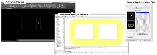
This is where the Midas General Section Designer will come in handy since this tool can analyze all kinds of general sections.
3. How to Navigate Through the midas General Section Designer
You can access your General Section Designer (GSD) in the Tools tab of your Midas Civil.
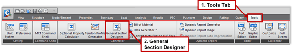 Figure 3.1 Tools Tab > General Section Designer
Once you open your GSD, the graphic user interface (GUI) looks like this:
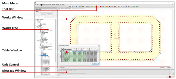 Figure 3.2 GUI of midas GSD
You have the Main Menu and the Tool Bar for the different functions to set your parameters such as the material, loadings, rebars, and the sectional drawing.
And just like other Midas Software, we also have here the Works Tree. This summarizes everything on your model, and it also acts as easy access to check and modify your work.
The Works Window shows the current section that you are working with.
The Message Window acts as a communication between the user and the software.
Then the Unit Control. This is where you are going to set the unit of measurement that you will consider on your work.
4. How to Set the Parameters for the User's Section
You have two ways to define your section here in the GSD.
4.1. Midas Link - link your midas Civil file then import your desired section.
4.2. Manual Definition.
4.1 Midas Link
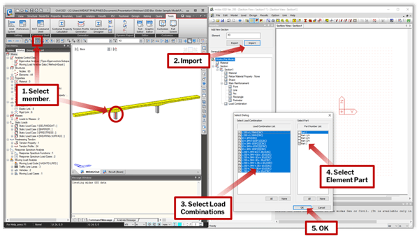
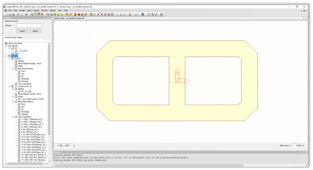
When you link your Midas Civil file in the GSD (Link tab in GSD > Midas Link). You can then import the section that you want to analyze, and GSD will adapt all the parameters that you set in Midas Civil (excluding the reinforcement).

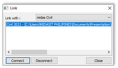
When you link your Midas Civil file in the GSD (Link tab in GSD > Midas Link). You can then import the section that you want to analyze, and GSD will adapt all the parameters that you set in Midas Civil (excluding the reinforcement).
4.2 Manual Definition
There are various functions that you can do to define the section that you want to design
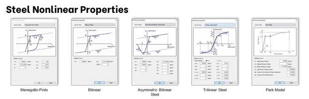
4.2.1 Material (Model tab > Material)
This function has a database of steel and concrete materials from various standards that are readily available for your choosing. The nonlinearity of your material may also be defined.
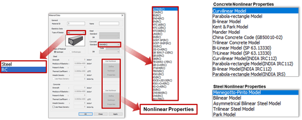
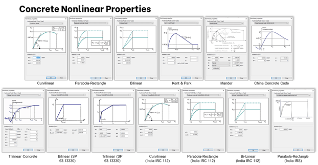 Figure 4.6 Concrete nonlinear properties
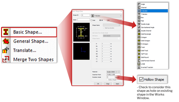
4.2.2 Shape (Model Tab > Shape)
There are three (3) ways to define your section in GSD. The first is by importing from Midas Civil which is already shown in Section 4.1 of this article.
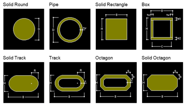
The second is by choosing from the database of Basic Shapes which is somehow similar in Midas Civil’s Section Property User/DB tab. The difference here is that you need to define your Material directly to the shape, then instead of offset, here, you will define the Insertion Point to assign the location of your shape in the Works Window. You can also rotate your shapes accordingly.
You also have the checkbox below to consider the shape as Hollow Shape. This will create holes in the solid shapes that will intersect in the Works Window.
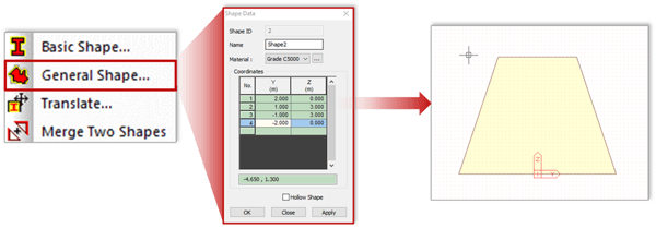
Third way is by defining the coordinates of your shape using the General Shapes. Just like in Basic Shape dialog box, you also need to define the material here, assign insertion point, rotate, and consider the shape as Hollow Shape.
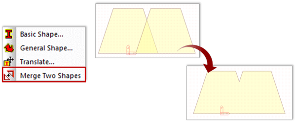
You can also modify your shapes using the Translate and the Merge Two Shapes functions. The Translate function moves or copies existing shapes using an equal/unequal distance that you define.
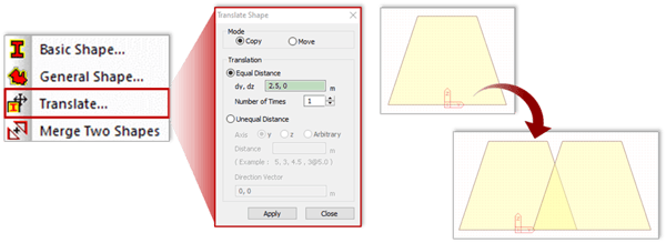
Then, with the use of the Merge Two Shapes functions, you can combine existing shapes that intersect into one.
Then, with the use of the Merge Two Shapes functions, you can combine existing shapes that intersect into one.
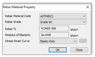
4.2.3 Rebar (Model Tab > Rebar)
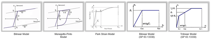
The functions to define your reinforcements are here. Use the Rebar Material Property function to define the material of your reinforcement. Linear and Nonlinear stress-strain curves can also be defined in your rebar material.
Various methods are available in order to assign the location of your rebar, namely:
a. Point Pattern
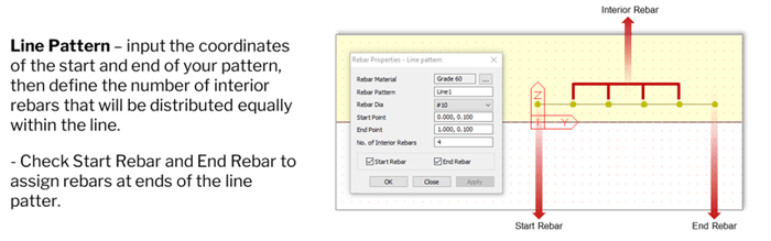
b. Line Pattern
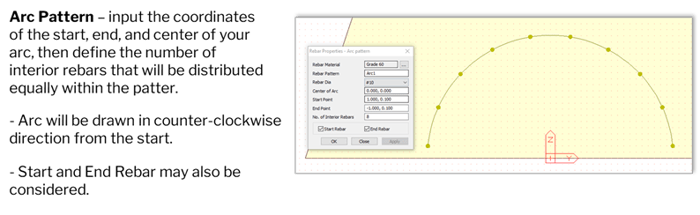
c. Arch Pattern
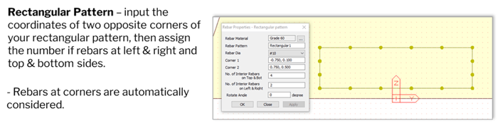
d. Rectangular Pattern
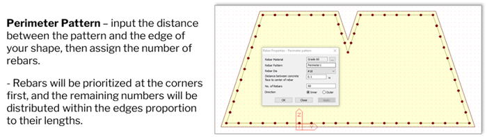
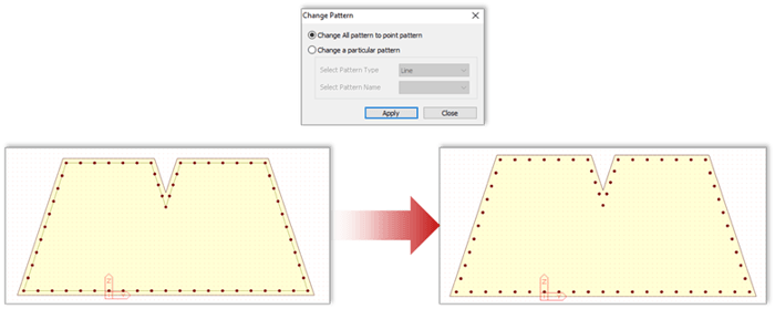
e. Perimeter Pattern
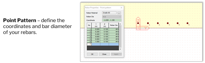
Then, if you want to modify specific rebars from these patterns, you can convert them to Point Patterns and then modify the rebars individually.
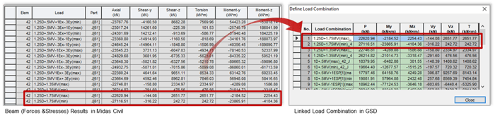
4.2.4 Load Combination (Load Tab > Define Load Combination)
This is used to define the load combinations that you want to apply in your section. You can input manually or adapt the load combination from your midas Civil using the Midas Link function.
In GSD, the sign convention for axial forces is opposite to midas Civil. Therefore, GSD will automatically convert the sigh of your axial forces in midas Civil from (+) to (-), and vice-versa.
Also, take note that GSD only analyses axial forces and bending moments only.
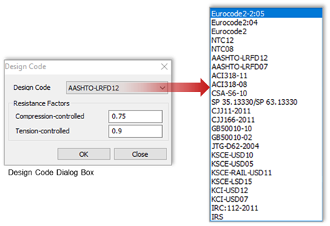
4.2.5 Design
In terms of design, you can choose from the various codes available in the database in Design Option (Option Tab > Design Option), and this will be the basis for the computation once you perform your design.
Once all the parameters are set and you have chosen the code that you want to consider, you can now perform your design using the Design Section (Design Tab > Design Section) function and results will be generated afterward.
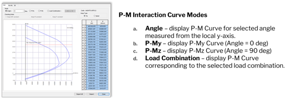
5. How to Generate Results in General Section Designer
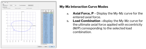
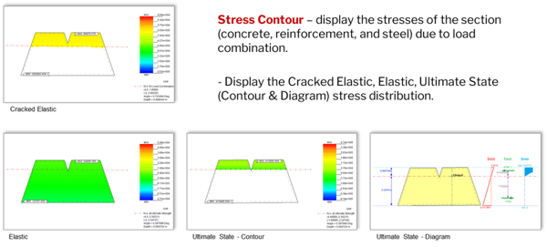
Once the design is successfully performed, you can now check your results for the Interaction Curves, Moment-Curvature Curve, and Stress Contours.
%20Interaction%20Curve.png?width=600&name=Image%205.3%20P-My-Mz%20(3D)%20Interaction%20Curve.png)
%20Moment%20Curvature%20Curve.png?width=600&name=Image%205.4%20P-My-Mz%20(3D)%20Moment%20Curvature%20Curve.png)
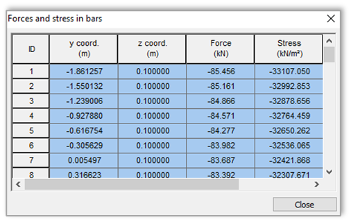
Forces and Stresses in each rebar are also available in table format (Excel compatible) based on the active stress contour that you are in.
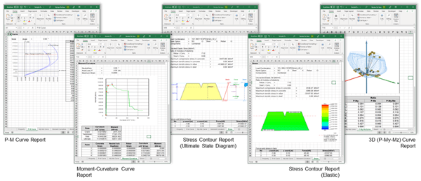
Lastly, you can generate all these results in Excel format with all the values and figures presented properly.


.png)
/2020%20Pics%20for%20drafts/Moving%20Load%20All%20You%20Need%20to%20Know-1.jpeg)
/MC%2004%20Section/How%20to%20Define%20Section%20Properties%20in%20Various%20Bridge%20Design%20Conditions%20345%20240.png)
/345%20240/Application%20of%20Links%20in%20Bridge%20FE%20Models.png)