Get Started midas Civil
 Featured blog of this week

Please fill out the Download Section (Click here) below the Comment Section to download the Complete Guide to Seismic Anlalysis
💡 You can explore more about seismic analysis of underground structures here (click)
Deformation Method
*Click the content to move to the section
1. What is the Seismic Deformation Method?
2. How is Seismic Design Performed Using the Seismic Deformation Method?
2-1. Modeling of the Soil-Structure Interaction System
2-2. Determination of the Base Level
2-3. Determination of the the Coefficient of Subgrade Reaction
3. Do other Countries Also Use the Seismic Deformation Method?
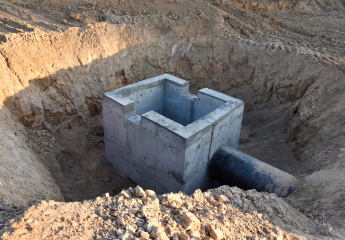
Underground structures such as Common Utility Tunnel, underground utilities, underground railways, etc., are in contact with the ground. Therefore, the response of these structures during an earthquake shows a different trend compared to the response of above-ground structures, which is primarily influenced by the natural period of the structure.
Most underground structures are hollow inside (i.e., they have an empty space), so the apparent unit weight of the structure per unit volume is generally equal to or smaller than that of the surrounding medium, which is the ground. Additionally, underground structures cannot vibrate freely due to the surrounding ground, resulting in significantly higher damping compared to above-ground structures. The displacement behavior also occurs in a manner similar to ground vibration. In other words, during an earthquake, the response of underground structures is known to be strongly influenced by the relative displacement of the ground generated by the surrounding medium rather than the inertial force caused by the mass of the structure.
1. What is the Seismic Deformation Method?
The Seismic Deformation Method is a design approach for seismic resistance of underground structures. It is used when the unit weight of the structure per unit volume is smaller than or equal to that of the surrounding medium. The Seismic Deformation Method statically calculates the stresses induced in underground structures by applying the displacements generated in the ground during an earthquake. In the "Guidelines for Seismic Performance Evaluation of Existing Facilities(Common Utility Tunnel) (2020.6, Ministry of Land, Infrastructure and Transport)," it is specified that the analysis of structures should consider the relative horizontal displacements, accelerations, and stresses in the free-field ground (where no structure exists) using a structural and ground analysis model (typically, the structure is modeled as frame elements, and the ground is modeled as spring elements).
In terms of converting dynamic ground motion into static analysis, this method is similar to the intensity-based approach. However, it fundamentally differs in that it first determines the displacements of the surrounding ground induced by seismic motion and then calculates the stresses in the underground structure based on these displacements, rather than determining inertial forces like in the intensity-based approach.
2. How is Seismic Design Performed using the Seismic Deformation Method?
The analysis procedure for seismic design of underground structures using the Seismic Deformation Method is as follows:
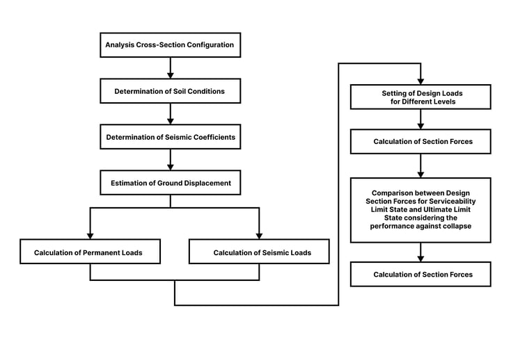
1) After setting the cross-section, the seismic coefficient is determined based on the soil conditions.
2) The maximum displacement amplitude of the ground is determined. When estimating the displacement amplitude of the ground, the design response spectrum at the foundation level is used by converting the existing acceleration response spectrum into a velocity response spectrum, and it is important to consider the velocity response spectrum calculation for each performance level.
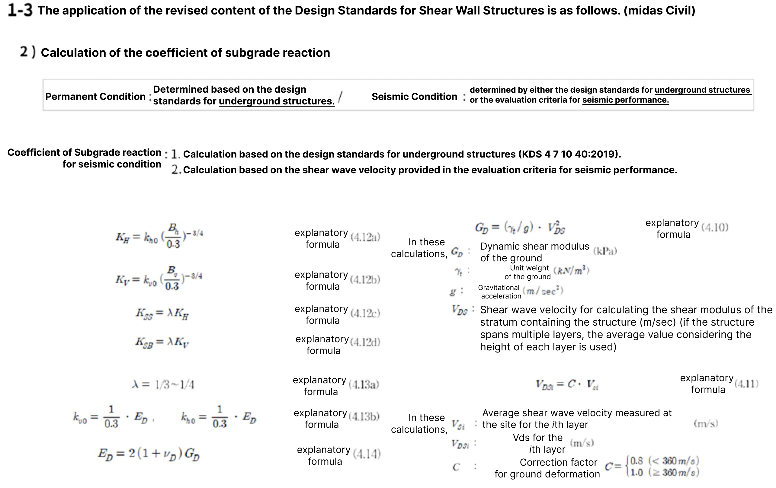
3) The Coefficient of Subgrade Reaction is determined based on the soil conditions.
4) The section forces caused by the permanent loads and seismic loads on the configured cross-section are calculated. In this case, the seismic load is determined by considering the most unfavorable stress, displacement, or other effects on the underground structure, and the comparison of section forces is repeated to determine the optimal section.
5) The calculated section forces are repeatedly compared with the design section forces caused by permanent loads to determine the optimal section.
💡 Want to Learn More about the Coefficient of Subgrade Reaction? (click)
2-1. Modeling of the Soil-Structure Interaction System
Modeling and analysis using the seismic deformation method are based on 2D cross-sectional modeling and analysis principles. However, in cases where there are abrupt changes in the ground conditions, it is necessary to consider longitudinal effects as well. Figure 2 illustrates the concept of the seismic deformation method, and the loads that need to be considered in the method include loads induced by natural ground displacement, shear forces generated in the surrounding soil of the structure in its natural state, and inertial forces of the structural elements.
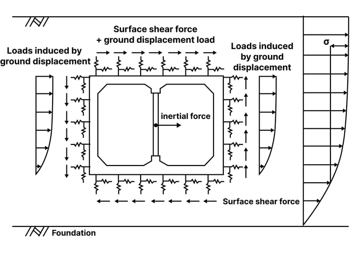 Figure 2. The concept diagram of the Seismic Deformation Method
In the seismic deformation method, the ground-structure system is represented by a structural model supported by the ground reaction coefficients around the structure, as shown in Figure 3. By applying the ground reaction coefficients, the natural ground displacement is imposed, and the resulting shear forces at the structure's location in the natural ground (interface shear forces) are applied to the structure. In this figure, K_H and K_V represent the horizontal and vertical ground reaction coefficients, while K_SS and K_SB represent the shear ground reaction coefficients for the side walls and top/bottom slabs, respectively.
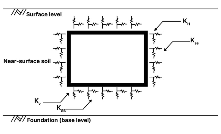 Figure 3. Modeling of the structure using the coefficient of subgrade reaction and frame elements.
2-2. Determination of the Base Level (Foundation)
To apply the Seismic Deformation Method, it is necessary to determine the displacement of the natural ground. For this purpose, the near-surface soil above the bedrock is replaced with a free-field accelerometer to determine the displacement of the natural ground.
In seismic analysis using the Seismic Deformation Method, the term "base level(foundation)" refers to the ground that extends widely beneath the target structure, with minimal changes in properties beyond a certain depth and with sufficient stiffness. It typically refers to bedrock with a shear wave velocity of 760 m/s or higher, and the upper surface of the bedrock is defined as the base level(foundation). In the Seismic Deformation Method, the seismic loads on the structure are determined based on the design velocity response spectrum at the base level.
Design Ground Motion
When using the Seismic Deformation Method for seismic analysis, the "General Guidelines for Seismic Design of Common Utility Tunnel" specify that the ground displacement should be determined based on the design velocity response spectrum at the base level.
The design velocity response spectrum at the base level refers to the velocity response spectrum at the base level derived from the response of the near-surface soil to the motion of the bedrock, considering the inherent period of the near-surface soil at the base level.
The design acceleration response spectrum due to bedrock motion is equivalent to the design acceleration response spectrum for rock ground specified in KDS 17 10 00: General Guidelines for Seismic Design. Therefore, the velocity response spectrum values can be calculated by multiplying the acceleration spectrum values for the ground's inherent period (Ts = 1.25 Tg), considering the performance level-specific damping ratio, by the amplification factor (Cd) for damping correction. Ground displacement can be determined using the single cosine method or double cosine method based on the design velocity spectrum.
In addition to ground displacement, the Seismic Deformation Method also considers the inertial force of structural elements. The inertial force is calculated by multiplying the acceleration at each depth of the structural element by its mass.
The acceleration of the ground at each depth is determined by extending a straight line from the design horizontal acceleration (S) at the base level to the horizontal seismic acceleration at the ground surface (Kh).
The design horizontal acceleration at the base level (S) is calculated by multiplying the hazard coefficient (I) corresponding to the seismic performance level and the seismic zone coefficient (Z) for the design response. The design horizontal acceleration at the ground surface is calculated by multiplying the amplification factor (Fa) for short-period ground response according to the soil classification. Finally, the inertial force is calculated by multiplying the acceleration at each depth and the mass of each element.
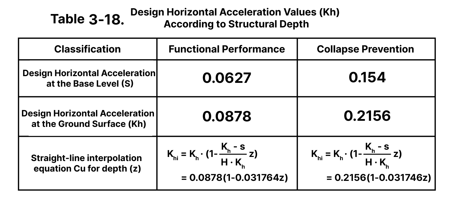 Table 3-18. Design Horizontal Acceleration Values (Kh) according to Structural Depth
2-3. Determination of the Coefficient of Subgrade Reaction
In seismic analysis using the seismic deformation method, it is crucial to accurately calculate the ground reaction coefficients. If the ground reaction coefficients are underestimated, it can lead to an underestimation of the seismic effects.
3. Do other countries also use the Seismic Deformation Method?
The seismic analysis of Common Utility Tunnel, as mentioned in the Design Standards for Common Utility Tunnel (KDS 29 17 00:2021), Section 4.5 on Seismic Analysis and Design, is typically performed using either the Seismic Deformation Method or the Response History Analysis Method.
For diaphragm Common Utility Tunnel, the Seismic Deformation Method is commonly used as the standard analysis method for seismic analysis of the Common Utility Tunnel. However, Response History Analysis may be used in cases that require more detailed investigation.
💡 Seismic Deformation Method
|