Get Started midas Civil
 Featured blog of this week

Please fill out the Download Section (Click here) below the Comment Section to download the Model Files
Bearing Arrangement for Curved Bridges
Table of Contents
1. Introduction
Let me start the article with a question, what is the most important component required to be designed for a bridge? The answers would vary from all the components of the substructure to the superstructure. A very minuscule portion of the engineers would care to mention the bearings. The most ignored element of the bridge is the bearing.
The bearing systems are the mechanical devices that transfer the loads from the main load-carrying members (superstructure) to the supports (substructure) of a bridge. The bearings transfer the vertical and horizontal actions to the substructure by accommodating rotational and translational displacements due to wind, seismic, temperature, permanent loads, etc. The bearings have very strict tolerances and shall be accurately designed to cater to the various load effects. A bridge bearing has the capability to significantly reduce the forces coming on the structure just by releasing the constraints in a particular direction. For example, the forces (moment, shear) coming onto the substructure due to longitudinal actions (such as temperature, creep, shrinkage, seismic, etc) can be reduced by simply providing bearing between the superstructure and substructure of the bridge.
In the past, we have seen several bridge failures due to bearing design faults, installation faults, and manufacturing faults. One such example is the Athwalines bridge collapse, Surat, India (2014), where, according to the news reports, one of the reasons for the failure of the simply supported curved bridge was the bearing design flaw.
To design bridge bearings the proper bearing arrangement shall be decided first, then the bridge shall be modeled and analyzed for the pre-decided bearing layout. Before moving forward let us discuss the bearing layouts for different types of bridges.
%20(Source-%20The%20Indian%20Express).jpg?width=571&name=Fig1.%20The%20Athwalines%20bridge%20collapse%2c%20Surat%2c%20India%20(2014)%20(Source-%20The%20Indian%20Express).jpg)
2. Bearing Layouts
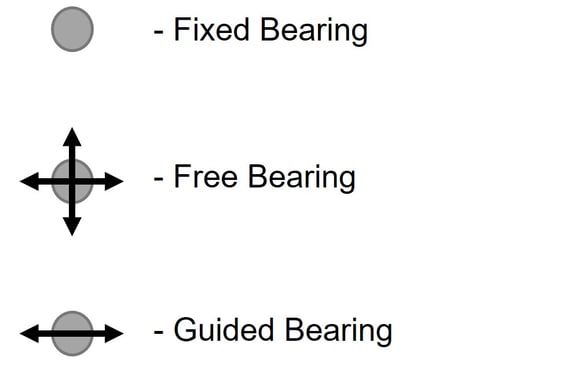
There are mainly three types of bearings in any bearing system, a. fixed bearing which resists horizontal forces in both the lateral direction (say X & Y), b. Guided/Sliding bearing which provides restrains in either X or Y direction, c. Free bearing which provides no restrains in either X or Y direction.
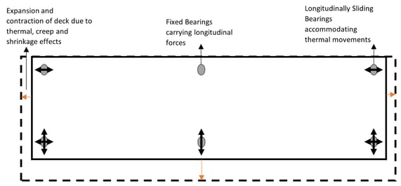
The various arrangements of these bearings are combined to create different bearing systems. For any bridge, the bearings are arranged such that the internal forces due to thermal, creep and shrinkage effects can be minimized in the deck.
Figure3 shows a typical bearing arrangement for the straight bridges, releasing all the constrained internal forces from the deck. The arrangement helps in the simplification and optimization of the deck design calculations. It is important to note that the expansion joints at the ends A and C shall accommodate the longitudinal displacements due to thermal, creep, and shrinkage considerations.
Similarly, for the curved bridges, different types of bearing arrangements are possible based on the following criteria, (i) to minimize the internal forces in the bridge deck and the bearings, and (ii) to avoid the translation of the expansion joint across the traffic direction. The following are the bearing systems for the curved bridges,
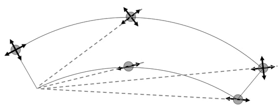
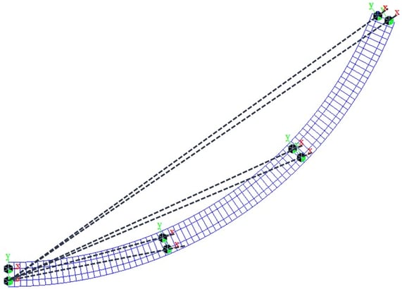
a. Radial bearing layout: The bearings are oriented such that the translation in the bearings is allowed radially with respect to the fixed bearing as shown in figure 4. This minimizes the internal forces in the bridge deck due to longitudinal actions (thermal, creep, and shrinkage effects) and reduces the bearing forces but the expansion joint at the abutment has translation along and across the traffic direction.
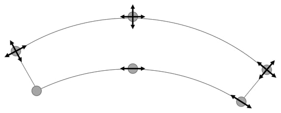
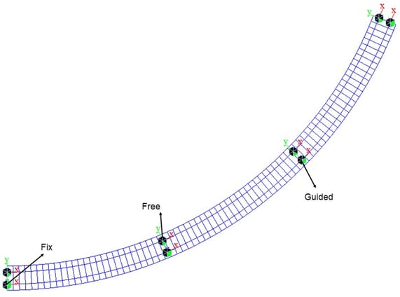
b. Tangential bearing layout: The bearings are oriented such that translation in the bearings is allowed tangential to the curve of the bridge as shown in figure 5. Due to this arrangement, the expansion joint at the abutment has translation only along the traffic direction but the bearing forces due to the longitudinal actions will be there.
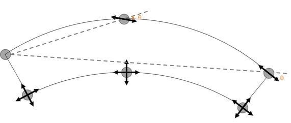
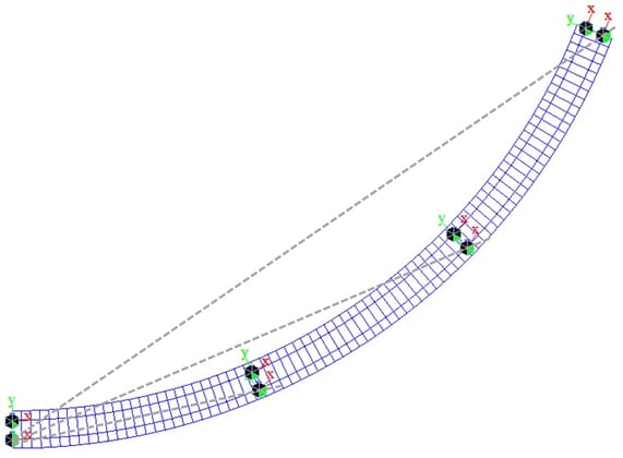
c. Hybrid bearing layout: The bearings are oriented tangentially at the abutment end to facilitate translation along the traffic direction. Whereas the intermediate guided bearings are oriented at an angle to the radial direction as shown in figure 6. As per this arrangement, the expansion joint at the abutment has translation only along the traffic direction and bearing forces caused by longitudinal actions are minimized.
3. Analytical Study
Until this point we have seen the theoretical working of different bearing arrangements, now let us study the effects by creating the numerical models of the same.
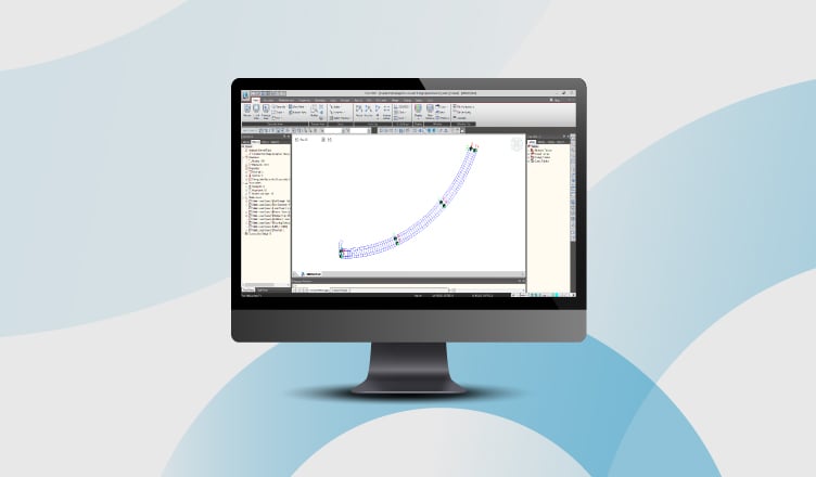
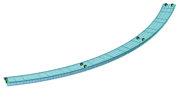
A 3@ 40 m span continuous curved steel composite bridge is modeled in midas Civil with the bearing layouts as discussed above for the comparison. The temperature load of 40 ﮿C is applied to the bridge elements to get the effect of expansion and contraction on the bearing systems of the bridge.
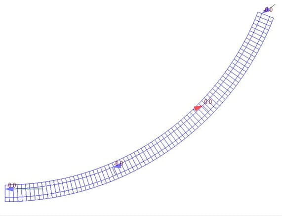
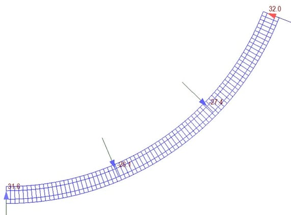
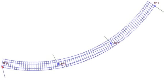
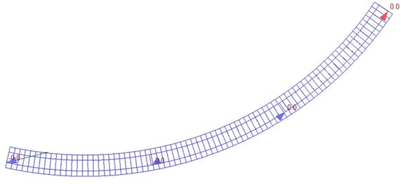
The superstructure is created as a grillage model using frame elements with longitudinal girders simulating the composite stiffness of the deck and the transverse girders simulating transverse deck stiffness. The constraints are provided at the bearing location as per the bearing system discussed above. The node-local axes are defined to orient the support constraint in a specified direction as shown in Figures 8, 9, and 10.
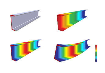
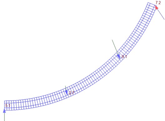
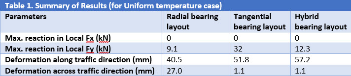
We have briefly discussed the modeling of the bridge with support constraints to simulate bearing arrangement. Now, let us compare the bearing reaction results and structure deformation results for the three types of bearing arrangements.
4.1. Radial Arrangement
4.2. Tangential Arrangement
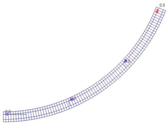
4.3. Hybrid Arrangement
5. Conclusions
After reviewing the results from the above comparison the following conclusion can be made, the hybrid type bearing arrangement suits the curved bridges better as it eliminates the translation across traffic at the expansion joint and at the same time minimize the forces in the bearing due to thermal, creep, and shrinkage effect.
Moreover, in a curved bridge, the inner bearings have lesser compression as compared to the outer bearing and the ratio of horizontal force to the minimum vertical force is a limiting criterion for the design of the bearings. If the ratio exceeds a predefined value (20-25%) then POT-PTFE or Spherical bearings cannot be used. Hence, these criteria further increase the importance of the bearing arrangement for a curved bridge.