Get Started midas Civil
 Featured blog of this week

Meshing
As structural engineers, whenever we need to analyze a complex structure, we turn to FEM (Finite Element Method) analysis for a quick solution with acceptable accuracy. The generalized beam element model is quite sufficient in most cases; however, there are a few instances in which we may need to go for detailed 3D finite element analysis. Few such cases are joint analysis, buckling analysis, material non-linear analysis, and so on. But hey, meshing even matters in simple linear analysis! Let’s have a look at the basic guidelines for meshing and the process of mesh convergence.
Table of Contents
1. Let's Talk About a Simply Supported Beam
One of the very basic things that we should clarify is the significance of discretizing. The calculations & output are all provided at nodes of an element. So, the elements need to be divided for obtaining the required results. Let’s consider a simply supported steel beam with UDL (Uniform Distributed Load) for linear analysis. The cross-section of the beam is 500mm x 50mm and it's 3m long. The beam is subjected to a UDL of 100 kN/m. With simple manual calculations, we can confirm the maximum bending moment and displacement for such a beam.
Max bending moment at centre = 100 x 32 / 8 = 112.5 kN/m
Max deflection at centre (no shear deformation) = 5 x 100 x 34 / (384 x 2.1 x 108 x 0.05 x 0.53/12)
= 0.964mm
Now let's have a look at the output that we’d obtain from a FEM-based software like midas Civil (Fig 1).
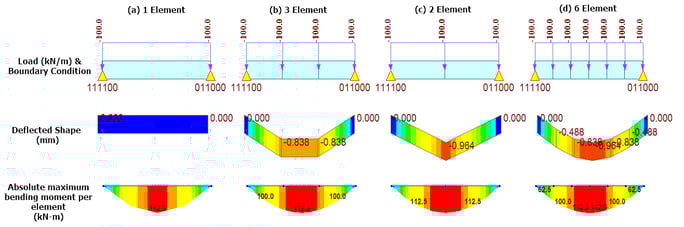
It can be noted that when the complete 3m is modeled with 1 element (Fig 1 - a), the deflection is 0mm. When the same is done as 3 elements (Fig 1- b), the peak deflection is missed. The peak deflection is fine when the 3m length is modeled with 2 elements (Fig 1- c); however, the deflected shape clearly is not what we’d practically expect to see. When this 3m length is modeled with 6 elements (Fig 1- d), the deflected shape of the beam and the peak deflection matches our expectation.
But what about the bending moments? Why is the maximum bending moment the same irrespective of the number of divisions?! I just mentioned earlier those calculations happen at nodes in FEM! Well, we get proper bending moments here because midas Civil internally divides each element into 4 equal parts to provide the results of the bending moment. Hence, peak moments are captured irrespective of the number of element divisions in this case. However, this is done only for linear analysis. If this is done for non-linear analysis as well, then the computational time will increase. Now, let's have a look at the bending moment results for non-linear static analysis (Fig 2).
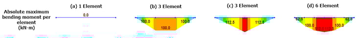 Figure 2 - Bending moment results of a simply supported beam - Non-linear Analysis
From Figure 2, it can again be noted that 1 element (Fig 2-a) & 3 elements (Fig 2-b) are missing the peak moments. 2 elements (Fig 2-c) is showing a bending moment diagram as we would expect for a concentrated load of 150kN, so that’s showing incorrect behavior, though the final output value is correct. Whereas the 6 element (Fig 2-d) is giving correct behavior even for non-linear analysis. So, always make a model with very fine mesh, correct? Not necessarily, but we’ll talk about that later.
2. Oversimplification for FEM Practitioners
One can be either a good FEM coder or user. If you are reading this article, you are probably in the latter category, like me. While there are jargons of mathematical equations that need to be solved to obtain a solution in a finite element system, an oversimplification can be made for easier understanding as a user. Any finite element model can be said to be nothing but a set of nodes connected via springs of different stiffness and all calculations are to obtain the final output at these nodes. In reality, the calculations happen at “gauss points” somewhere in the element and the results are then extrapolated to obtain the output at node locations, but as practitioners, we don’t need to know many details about that. So, we are clear that what matters to us is the stiffness connecting the nodes rather than the actual elements.
Oversimplification leads to another question. There can be many elements connected to one node and since the sizes are different, the output at the gauss point for each of these elements would be different. Hence, when the results are extrapolated at node location, this common node will have different results for each element! So, what’s the correct result?! The answer is, all of them! And yes, that is weird. To arrive at a single answer, we have a simpler way of averaging the results at the node and that also leads to smoother contours (Fig 3).
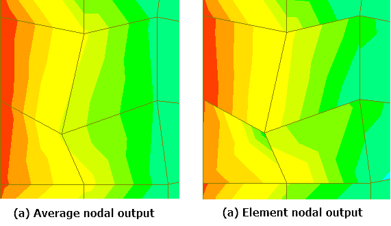
Figure 3 - Stress output contour in a plate mesh - Unrefined mesh
Great! Contours are fixed now, but is that still an acceptable answer? That’s where mesh refinement comes into the picture. With finer mesh, the difference in results at the common node will reduce and the solution will converge to the actual answer. Now, let’s have a look at the difference in the output of refined and un-refined mesh (Fig 4).
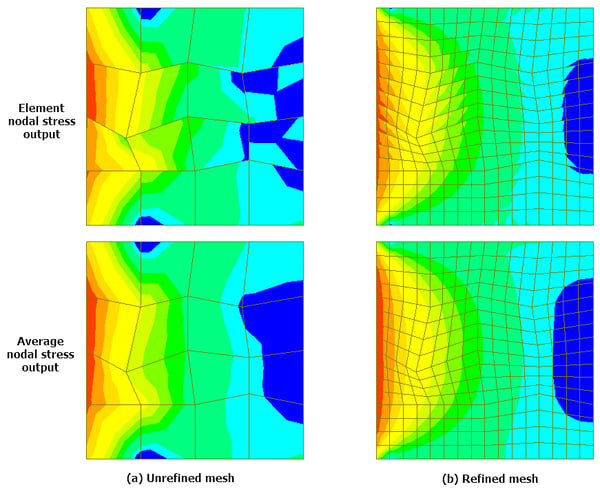
As it could be noted from the image above, refined mesh gives a contour that is quite comparable between average nodal & element output for most of the part, while huge variation in results is observed for unrefined mesh. Moreover, irrespective of skew in elements, the variation in results between the elements is quite low. So then, what’s the correct mesh size? Unfortunately, there is no common correct answer to this. The correct mesh size depends on many parameters like acceptable accuracy, computational time, meshing time (especially in a complex geometry), etc. You need to arrive at the correct mesh size depending on your desired output and the time available. However, a consensus is that when the variation in the desired output is less than 3% on refining the mesh, then that is an acceptable size.
Now we know that finer mesh leads to more accurate results, well in most cases. However, there may be instances where we are interested in a very specific output in a relatively large structure. And refining the complete structure mesh does not make much sense because the analysis time may exponentially increase! In such instances, we can make a coarser mesh or a different element altogether in the area which isn’t of our interest, and we can make a finer mesh in the region of interest. As an example, let's consider a steel tub girder, which needs to be accessed for non-linear buckling due to a unique loading condition. This is a 30m long girder and 2 models are made to check the buckling of this girder under a point load near the center span (Fig 5).
%20Global%20refined%20model%20and%20(b)%20Local%20refined%20model.png?width=650&name=Fig%205%20-%20(a)%20Global%20refined%20model%20and%20(b)%20Local%20refined%20model.png)
The analysis for global refined model was about 120 seconds while the local refined model was analyzed in about 32 seconds. The time taken for the complete refined model was 4 times that of the local refined model; however, the variation in buckling load results was less than 3%. For a larger, more complex model, the saving in resources can be significant!