Get Started midas Civil
 Featured blog of this week

Table of Contents
2. Integral Bridge Function – Abutment Spring
3. Integral Bridge Function – Pile Spring
1. Introduction
An integral bridge refers to a bridge in which the superstructure and the pier/abutment are integrated out of necessity. This integration implicates that there is no bearing that transmits force or displacement between the two structures.
An integral bridge is a kind of bridge on which expansion joint and bearings are not present to transmit forces/displacement between the superstructure and the substructure (abutment/pier) unlike in conventional bridges. The absence of bearing and expansion joints may lessen the total cost and ease the maintenance of the bridge.
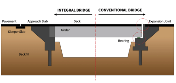
The main concern for integral bridges is the effect of varying temperatures as it causes the bridge deck to deform either contraction or expansion. These repeated contractions and expansion of the deck have a significant effect on the backfill adjacent to the abutment which causes a cycle of soil compaction and soil slide, which in effect causes the modulus of subgrade reaction and pressure distribution of the backfill to vary with depth.
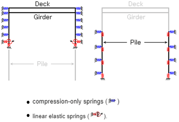
As this cycle continues infinitely, the modulus of subgrade reaction on the backfill becomes constant. With this, a formulation is proposed by Barry Lehane to calculate this behavior through soil springs to represent the interaction between the soil and the abutment/piles. You may download a PDF file at the end of this link for a quick reference (BM Lehane - Simplified Elastic Model for Restraining Effects of Backfill Soil on Integral Bridges).
In Midas Civil, Integral Bridge function is readily available to auto-calculate these soil springs based on Barry Lehane Calculation. This function will help you in assigning corresponding Compression-only Lateral Springs and Linear Elastic Springs in your abutment and piles by providing the parameters required by the function which will be discussed in this article.
2. Integral Bridge Function – Abutment Spring
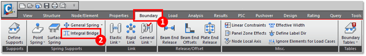
Integral Bridge function in Midas Civil is found on the Boundary tab, under the Spring Supports group:
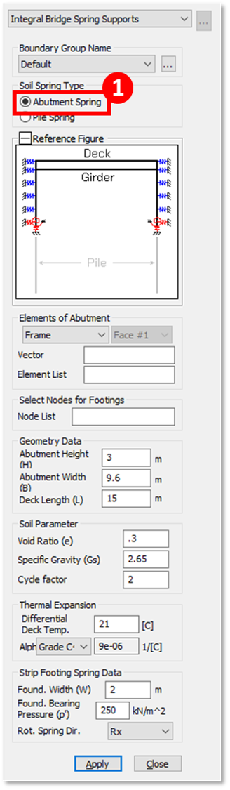
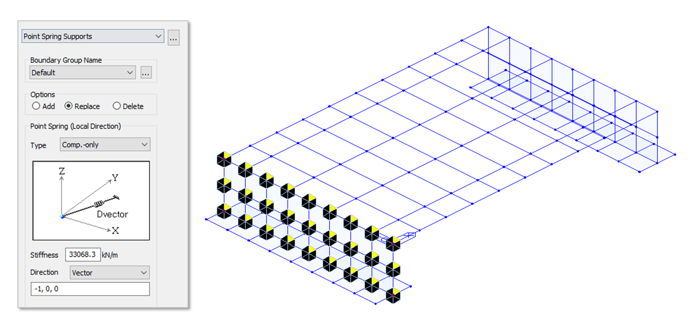
When the Abutment Spring option is selected as the Soil Spring Type, the function will look like this (below). Using this option, backfill soil will be represented by Compression-only springs and the bottom nodes of the abutment are assigned with Linear Elastic Links. Let’s break this function to fully understand how to input each parameter:
For the Elements of Abutment, you have four (4) options available, Frame, Planar, Solid Face, and Solid Nodes.
1. Frame – this is usually used if the abutment is a series of abutment columns. This is to be assigned on beam elements on your model. If Frame is selected, you need to define the Vector or the direction in which your line element will resist compression.
2. Planar – this is used if the abutment is modeled using plate elements. Direction is either Normal(+) or Normal(-), which pertains to the positive or negative side of the plate with reference to its Local Z. Compression-only Spring support will be defined on the side of the selected direction.
%20and%20Normal(-)%20Side%20of%20a%20Plate%20Element.png?width=627&name=Figure%202.3%20Normal(+)%20and%20Normal(-)%20Side%20of%20a%20Plate%20Element.png)
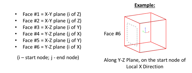
3. Solid(Face) & Solid(Nodes) – This is used if the abutment is modeled as a solid element. The difference between the two is that Surface Spring will be assigned for Solid(Face), and Point Springs will be assigned when Solid(Nodes) is selected. Direction is automatically in Normal, but you need to select the specific face of the solid where you want to assign the Compression-only Spring Support. To properly identify the Face#, below is a guide with reference to the local axis of the solid element.
For the Elements List, just select all the elements that represent your abutment where Compression-Only Lateral Springs are to be defined.
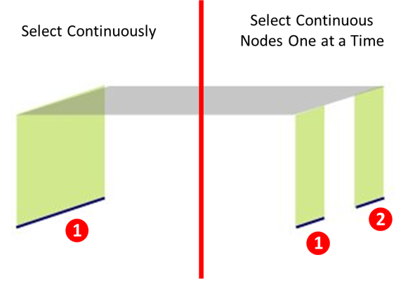
For the Node List in Select Nodes for Footing, select the nodes to which the Linear Elastic Spring for the foundation is to be assigned. Just take note that these nodes should be on a continuous straight line. In case nodes are in a straight line but not continuous, just select continuous nodes one at a time.
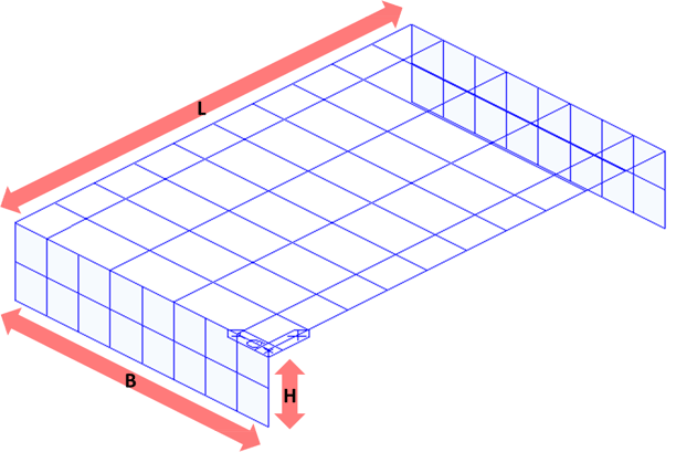
The Geometry Data are dimensions with reference to your model. You can either input manually or you can just select the end-to-end nodes to define these distances since these are all dynamic input (you know that it is dynamic when it turns green when you activate the text box).
1. Abutment Height (H)
2. Abutment Width (B)
3. Deck Length (L)
Soil Parameters are properties of the backfill soil.
1. Void Ratio (e) – the ratio between the volume of voids versus the volume of soil.
2. Specific Gravity (Gs) – the ratio between the unit weight of the backfill soil versus the unit weight of water.
3. Cycle Factor (fcyc) – based on the test conducted by Cosgrove and Barry Lehane, this assessed at about 2. This factor is used in the empirical formula which accounts for the state after infinite cycles of deck expansion and contraction due to temperature variation. To fully understand this, a downloadable file is provided for the study conducted by Cosgrove and Barry Lehane (Cyclic Loading of Loose Backfill Placed in Adjacent to Integral Bridge Abutment).
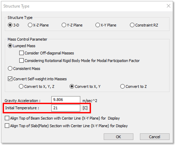
In the Thermal Expansion part, you need to define the Differential Deck Temperature which is the temperature increment the deck will experience. For this, Initial Temperature needs to be defined on your Structure Type.
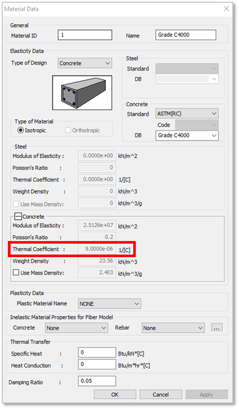
The Alpha (α) is for the Thermal Expansion Coefficient of the deck. You may input this manually, or you can also select the material property used in the deck to adapt the Thermal Coefficient defined in the Material Data or from the Database.
Lastly for the Abutment Spring is the Strip Footing Spring Data. Foundation Width (W) from the word itself is the width of your foundation or pile cap. Foundation Bearing Pressure (p’) can be taken as the soil or foundation bearing capacity in terms of pressure (per unit area). Last is the Rotational Spring Direction or the rotational direction of the foundation. Select Ry if the longitudinal direction of your foundation is along Y-direction or select Rx if the longitudinal direction is along the X-direction.
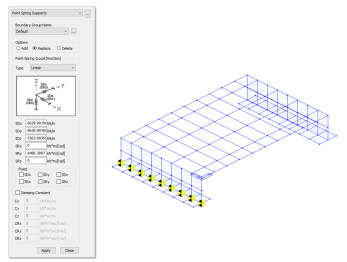
Once all these parameters are properly set, your abutment soil springs will now be assigned to your model look like the example below.
3. Integral Bridge Function – Pile Spring
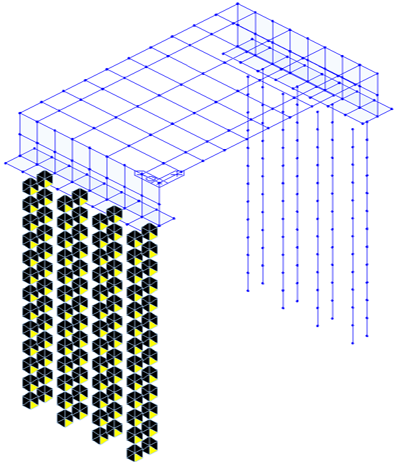
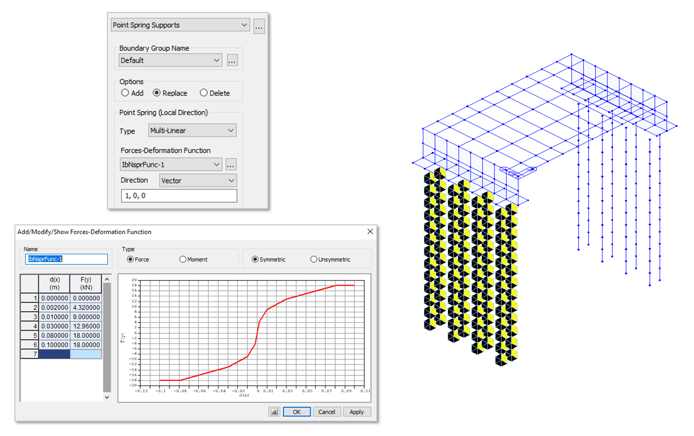
Integral Bridge Function in Midas Civil looks like this (below) when Pile Spring is selected for the Soil Spring Type. This function will help you assign spring supports along your pile representing the adjacent soil to it (Symmetric Nonlinear Lateral Elastic Links and Vertical Linear Elastic Springs).
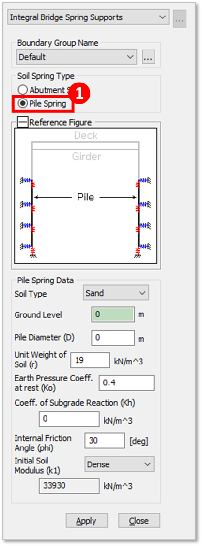
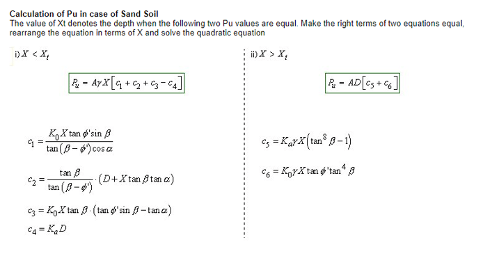
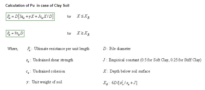
Soil Type is classified as either Sand, Soft Clay, or Stiff Clay. Depending on the soil type, calculation of stiffness varies.
Ground Level is the level of the ground with reference to the Z-coordinate.
Pile Diameter is simply the diameter of each pile.
Unit Weight of Soil, Earth Pressure Coefficient at Rest (Ko), Coefficient of Subgrade Reaction (Kh), and Internal Friction Angle (phi) are properties of your soil adjacent to you pile. Please take note that these properties vary for each soil later, so you need to define these properties for each soil layer one at a time.
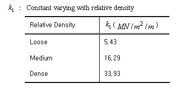
For Sand Soil Type, Initial Soil Modulus (k1) needs to be defined. This is a constant determined based on the relative density either Loose, Medium, or Dense. This will determine the stiffness of the nonlinear elastic lateral spring for the soil adjacent to the pile.
For Clay Soil Type, 1/2 Strain at Maximum Stress Point in Triaxial Compression Test (E50) needs to be defined. This value is taken directly from laboratory tests.
In the absence of these kinds of tests on your soil layers, suggested values of E50 for Soft to Firm clays are 0.02 and 0.01 respectively. For Stiff to Hard clays, suggested values are 0.005 and 0.004 respectively (Sulivan et at, 1980).
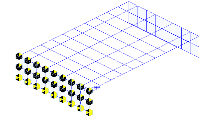
Once all these parameters are properly set, point spring supports will be defined on your selected piles and it will look like this on your model.
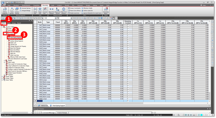
You can check the auto-calculated spring stiffnesses in two ways. One is by checking the properties of each spring support using the Works Tree Menu (Right-click on the Spring Support > Properties) or you can check these Spring Supports in table format using the Tables Tree Menu (Boundaries Group > Double-click on Point Spring Supports).
Some downloadable PDF files are available in this article if you want to cross-check the auto-calculated spring supports performed by Midas Civil. Some of the calculations can also be referred on our online manual by using this link. You may also read this article entitled Integral Bridge Analysis: Forder Valley Viaduct Bridge for a case study where the Integral Bridge Function of Midas Civil is utilized.