Get Started midas Civil
 Featured blog of this week

The Importance of Soil-Structure Interaction in midas Civil
Table of Contents
3. Dynamic Properties Comparison of the Bridge
Due to the peculiar site soil conditions, as the great deformation capacity of its clay layers, the effects of soil-structure interaction must be considered. Those effects consist of a set of kinematic and inertial effects that occur between the structure and the soil because of its deformation capacity at seismic response excitation.
The Soil-Structure Interaction (SSI) modifies the dynamic properties of the structure assumed, in a first step, with a non-deformable base. This effect is of utmost importance for flexible structures (as bridges) located in soft soils with long site periods.
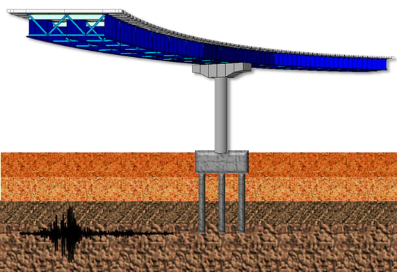 Figure 1 Soil-Structure Interaction for bridges on soft soils
1. Introduction
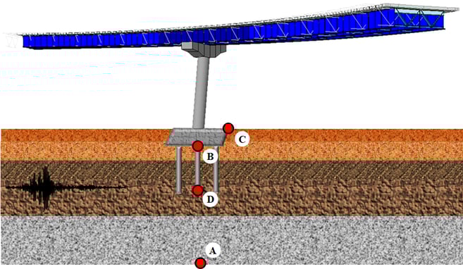
The Soil-Structure Interaction (SSI) effects have three essential concepts (figure 2), and they are necessary to understand the increase of the fundamental period of the bridge and its associated damping:
a) Site Effect: It is the seismic response influenced by geological and topographical local conditions and, more importantly, by the mechanical properties of the soil. That is, since the soil stratum overlying the bedrock (point A) will have different properties, it means that the movement between points A, B and C will be different, even in the absence of the foundation.
b) Kinematic Interaction: It is the modification of the free-field ground motion, due to the presence of the foundation. That is, it considers that the foundation, which is an element with greater stiffness than the soil, lead a rotational excitation at the base of the foundation system (point D), since points C and B cannot move independently of each other. That is, translational movements and displacements are generated due to rotations in the soil-foundation system. Those two movements correspond to a rigid body movement of the superstructure relative to the soil.
c) Inertial Interaction: It is the relative displacement of the foundation with respect to the ground, produced by the inertial forces of the superstructure on the soil-foundation system. The inertial interaction can increase or decrease the design forces with respect to the values corresponding to a fixed base, depending on fundamental periods and damping of the bridge and also depending on the design spectrum and their values associated to the two parameters before mentioned. That is, the displacements and strength demand increase or decrease depending mainly on the period relationship between the bridge and the soil; however, these effects decrease as the deformation capacity of the structural system is greater (Avilés and Perez-Rocha 2005).
2. Boundary Conditions
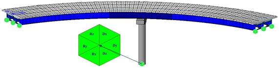
The boundary conditions in midas Civil are distinguished by nodal and element boundary conditions. Among the nodal boundary conditions are supports, the spring supports and the elastic links. The supports function may be used to constrain specific nodal displacements or rotations. These nodal constraints are applicable for 6 degrees of freedom with respect to the Global Coordinate System (GCS) or the Node local Coordinate System (NCS). Figure 3 illustrates a bridge with fixed base in the base of the pier, modeled as a general beam element.
Elastic boundary elements are used to define the stiffness of foundations. Spring supports at a node can be expressed in six degrees of freedom, three translational and three rotational components with respect to the Global Coordinate System (GCS). The translational and rotational spring components are represented in terms of unit force per unit length and unit moment per unit radian respectively. Spring supports are readily applied to reflect the stiffness of columns, piles or soil conditions. When modeling sub-soils for foundation supports, the modulus of subgrade reaction is multiplied by the tributary areas of the corresponding nodes. In this case, it is cautioned that soils can resist compressions only.
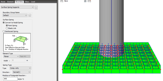
Midas Civil provides Surface Spring Supports to readily model the boundary conditions of the subsurface interface. This Spring is selected in Model>Boundaries>Surface Spring Supports and the modulus of subgrade reaction is specified in each direction (Figure 4). The soil property is then applied to the effective areas of individual nodes to produce the nodal spring stiffness as a boundary condition. In order to reflect the true soil characteristics, which can sustain compression only, Elastic Link (compression-only) is selected and the modulus of subgrade reaction is entered for the boundary condition.
The axial stiffness of spring supports for columns or piles can be calculated by EA/H, where E is the modulus of elasticity for columns or piles, A is Effective cross-sectional area, and H is Effective length. Generally, boundary springs at a node are entered in the direction of each degree of freedom. For more accurate analyses, however, additional coupled stiffness associated with other degrees of freedom needs to be considered. That is, springs representing coupled stiffness may become necessary to reflect rotational displacements accompanied by translational displacements. For instance, it may be necessary to model pile foundation as boundary spring supports. More rigorous analysis could be performed by introducing coupled rotational stiffness in addition to the translational stiffness in each direction.
Singular errors are likely to occur when stiffness components in certain degrees of freedom are deficient after formulating the stiffness. If the rotational stiffness components are required to avoid such singular errors, it is recommended that the values from 0.0001 to 0.01 be used. The range of the values may vary somewhat depending on the unit system used. To avoid such singular errors, midas Civil thus provides a function that automatically assigns stiffness values, which are insignificant to affect the analysis results.
An integral bridge is one in which the bridge deck and its supporting abutments and piers are integrated without expansion joints to absorb the deformation of the bridge deck using the flexibility of the abutments and piers. To account for this characteristic of the soil, lateral springs are modeled as compression-only springs and vertical springs are modeled as linear elastic springs.
The pile spring supports assign springs for the soils adjacent to piles. Lateral springs for the soils adjacent to piles are modeled as symmetric nonlinear elastic springs and vertical springs for the soils adjacent to piles are modeled as linear elastic springs. The stiffness of soil springs is automatically calculated and entered into Point Spring Supports.
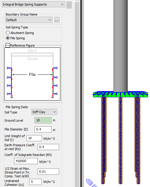
Figure 5: Bridge with pile spring support
As a first step, you need to select the frame element to which the pile springs have to be assigned. Soil Types are classified into Sand / Soft Clay / Stiff Clay. Depending upon the selected Soil Type, stiffness calculation method will be different. The ground Level is the Z coordinate of ground. Other parameters need to be set as Pile Diameter (D), Unit Weight of Soil (γ), the coefficient of earth pressure at rest (K0), the modulus of subgrade reaction (Kh), the angle of internal friction of soil (Φ) and the initial soil Modulus (k1), that is a constant determined according to the relative density. All these parameters determine the stiffness of nonlinear elastic lateral springs for the soils adjacent to piles. The elements to which the pile springs are assigned should have their local axis aligned in the same direction.
3. Dynamic Properties Comparison of the Bridge
The use of different support conditions at the base of the bridge will result in a change in the dynamic properties of the structure. Three different models are compared where the boundary conditions are varied; the model of figure 6a takes into account a completely fixed base; the model in figure 6b has the pier cap modeled with plates and the stiffness of the ground was modeled with the surface spring support function; and finally, the model in figure 6c has the pier cap and foundation piles modeled using the Surface Spring Support and Pile Spring Support features respectively.
From these figures, the stiffest model is the one that considers the base of the bridge as fixed with a fundamental period of 1.07 s (figure 6a), because the stiffness of the soil is modeled as infinitely rigid. However, the model that considers the stiffness of the ground (895 kN/m3 modulus of subgrade reaction) and only the pier cap is modeled, it is the most flexible model with a fundamental period of 1.97 s (figure 6b).
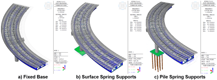
The use of the foundation piles and the soil stiffness properties with the pile spring support function, makes the model stiffer than the model with surface spring but without foundation piles (figure 6b), but more flexible where a fixed base is considered (figure 6a). More importantly, an integral bridge modeling (figure 6c) will result in a better control of the pitch effect and it can be corroborated in table 1, where the mass participation percentage is reduced for the values RX and RY, to less than 20% for the first three vibration modes. Another important difference is that most of the mass participation percentage in DX and in DY changes according to the boundary conditions modeled.
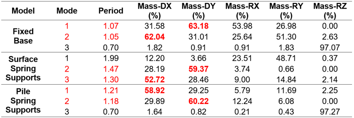
Table 1. Dynamic properties comparison of the bridge
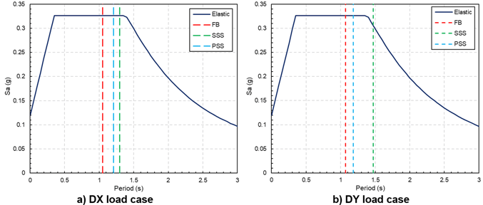
The change in the participation of the mass, in each direction of analysis, because of the changes in the boundary conditions increase or reduce the fundamental period among the models. Moreover, the values for the response spectrum cases in the design of structural members changes too. For example, the model with soil stiffness modeled with the Surface Spring Supports function (figure 7b, green line), its flexibility allows considering a lower value from the response spectrum case than the rest of the models compared. However, it is important to consider the displacements generated in each of the models for the design of the bridge so much for the maximum considered earthquake (MCE) as well as for frequent earthquakes.
4. Displacements Comparison of the Bridge
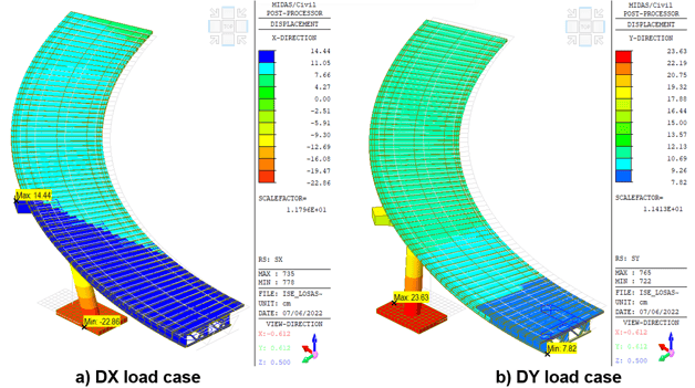
Figures 8, 9 and 10 compare the elastic displacements obtained with the response spectrum load cases with different boundary conditions. In the model with fixed base (figure 8), the displacements in the base are zero while the maximum displacements occur in the deck with an approximate magnitude of 10 cm for both the X and Y directions (figure 8).

When a boundary condition with surface spring supports is used, the maximum displacements in the deck increase to 14 cm for the X direction (figure 9a), while for the Y direction it is increased to 12 cm (figure 9b), compared to with the fixed base model. Moreover, the maximum displacements in the entire structure are at the pile cap with 23 cm approximately in both directions (figure 9), because in this model both the horizontal and vertical stiffness of the soil are considered.
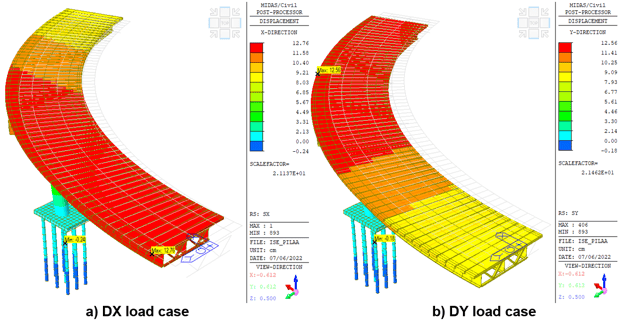
The use of foundation piles reduces the maximum displacements in the bridge deck compared to the model where only surface pier supports are used (figure 9). However, the displacements are still 25% higher (figure 10), compared to the model with a fixed base (figure 8). The maximum displacement at the pile head is 1 cm due to the small pitching effect that occurs due to the additional stiffness of the piles in the overall structural system.
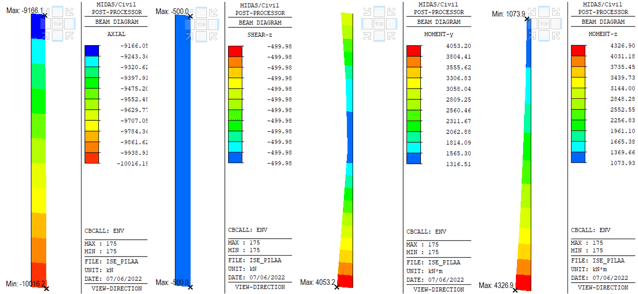
5. Force Elements Comparison of the Pile
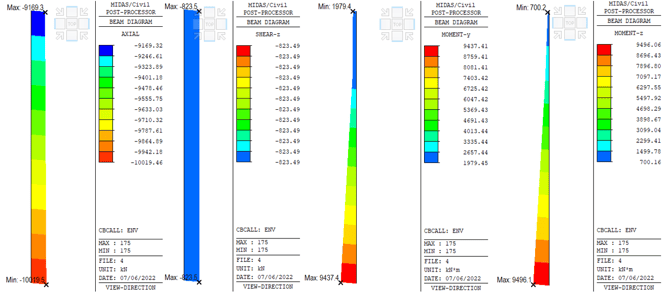
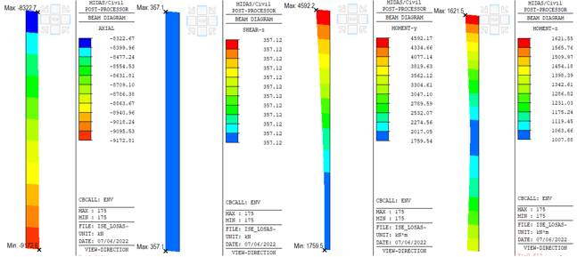
Figures 11, 12 and 13 show the maximum and minimum beam forces/moments that were obtained from the envelope load combination. From these figures, the axial load between the model with a fixed base (figure 11) and the model where the foundation piles are used (figure 13) are very similar to each other. Nevertheless, the maximum shear force occurs in the model with a fixed base (figure 11). However, the model where the foundation piles are modeled shows 57% less bending moment (figure 13), compared to the fixed base model (figure 11) in the local direction My. Finally, for the model where only the pile cap is modelled, there is 83% less bending moment in the local direction Mz (figure 12), compared to the model with a rigid base (figure 11).
The above results commented will lead to changes in the longitudinal and transversal rebar proposals to fulfill the demand from the load combinations in order to achieve the strength and deformation requirements impose by the code.
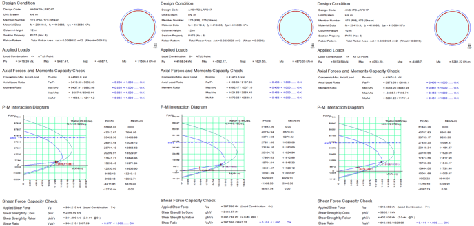
6. Pile Design Comparison
It is observed that for the fixed base model, an area of 370 cm2 for longitudinal rebar is needed to fulfill the strength demands, which represents 1.53% of the rebar ratio. However, when soil-structure interaction effects are used, the rebar area needed to fulfill the strength demand is reduced to the minimum possible, that is, 231 cm2 of longitudinal rebar (rebar ratio of 1%). Even when the minimum reinforcement is used, the demand/capacity ratio of the bridge pier is 45%. This result allows us to reduce the strength of the concrete section or reduce the cross-sectional area of the bridge pier.
7. Final Commentaries
The use of Soil-Structure Interaction (SSI) effects allows us to create a complete mathematical model of the bridge, that is, it allows us to model the superstructure, the substructure and the foundation. This integral bridge modeling allows us to know more realistic and accurate results of the structural behavior of a bridge on soft soils (sand, soft clay or stiff clay). In addition, the use of SSI effects modifies the dynamic properties of the bridge and the maximum expected displacements in the event of the maximum considered earthquake (MCE) or for frequent earthquakes.
In general, the use of SSI effects increases displacements because soil stiffness is considered but does not necessarily increase the amount of rebar area needed to fulfill code strength requirements. As can be seen in the comparison presented in this document, although the displacements increased by 25%, the demand/capacity ratio was reduced by approximately 55% for the same design conditions and only by varying the support conditions of the bridge.
8. References
Avilés, J y LE Perez-Rocha (2005). “Design concepts for yielding structures on flexible foundation”. Engineering Structures, No. 27, pp. 443–454.
MIDAS (2022), Integrated design systems for buildings and general structures, MIDAS Civil v.1.2, Midas Information Technology Co. Ltd.


-1.png)