Get Started midas Civil
 Featured blog of this week

This part checks the stability of the abutment with a spread footing. The stability review will follow the "AASHTO LRFD section 11 - Abutments, Piers and Walls". The Service Limit State and Strength Limit State will be reviewed following details below.
11.6.2 Movement and Stability at Service Limit State
11.5.2 Differential Vertical Settlement
11.6.2.3 Overall Stability
11.6.3 Bearing Resistance and Stability at Strength Limit State
11.6.3.2 Bearing Resistance
11.6.3.3 Overturning (Eccentricity Limits)
11.6.3.6 Sliding
🔖 Tips
The Overall stability is reviewed as a Service Limit State in AASHTO LRFD (SI) 2007; however, the overall stability is reviewed as a Strength Limit State in 9th Edition 2020.
Additionally, the 2007 standards use the term "Overturning," while the 2020 standards use "Eccentricity Limits."
A. Bearing Resistance
Bearing resistance is reviewed according to "AASHTO LRFD 11.6.3.2 Bearing Resistance". The bearing resistance is reviewed by comparing the vertical stress of the foundation floor surface calculated with factored loads at the Strength Limit State and the resistances (bearing resistance provided in the geotechnical report).
The standards provide methods for calculating soil pressure distribution for abutments supported on soil and rock.
The Bearing Stress of footing on soil
When a structure is supported by soil, the vertical stress is assumed to be uniformly distributed pressure, as shown in the figure below. The vertical stress will have a parabolic distribution for footings placed at shallow depths in the soil. However, the vertical stress distribution will be nearly uniform if the footing is placed deep enough.
In addition, assuming that the vertical stress is uniform regardless of the type of soil supporting the structure can lead to a conservative design for simplified footing design.
AASHTO LRFD Figure 11.6.3.2-1 Bearing Stress Criteria for Conventional Wall Foundation on Soil
The vertical stress can be calculated as follows:
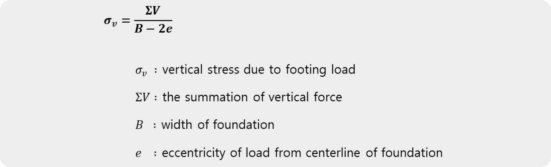
The vertical stress calculation 1
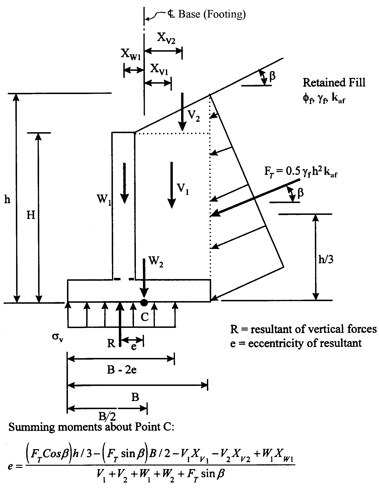
The eccentricity “e” can be calculated from the sum of the vertical force and the moment. The vertical force and moment that need to be considered in the eccentricity calculation are shown in the figure below.
The e and e0 can be calculated from the sum of the vertical force and the moment about point 'O'.
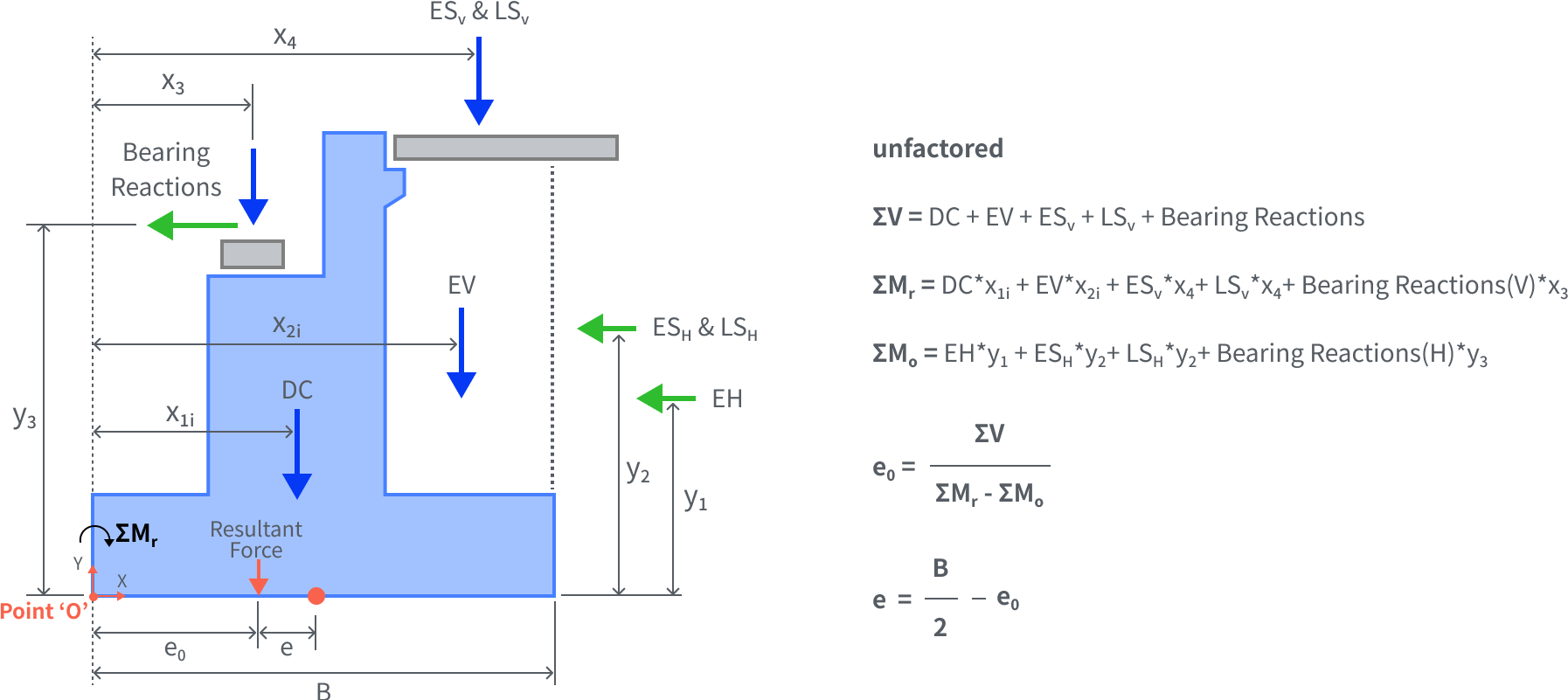 Eccentricity of Resultant Force
The Bearing Stress of footing on the rock
If the structure is supported by rock, the vertical stress is assumed as linearly distributed pressure, as shown in the figure. The maximum vertical stress occurs at the toe of the footing, while the minimum vertical stress occurs at the heel. This distribution varies depending on the e location where the resultant force is applied.
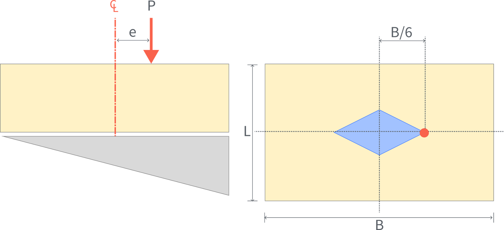
The location where the resultant force acts should be within the middle third of the footing width (e < B/6) for better design efficiency. Suppose the location of the resultant force is beyond the middle third of the footing width (e > B/6). In that case, a triangular stress distribution will occur, causing large compressive stress on one side, which can lead to problems such as soil failure or differential settlement.
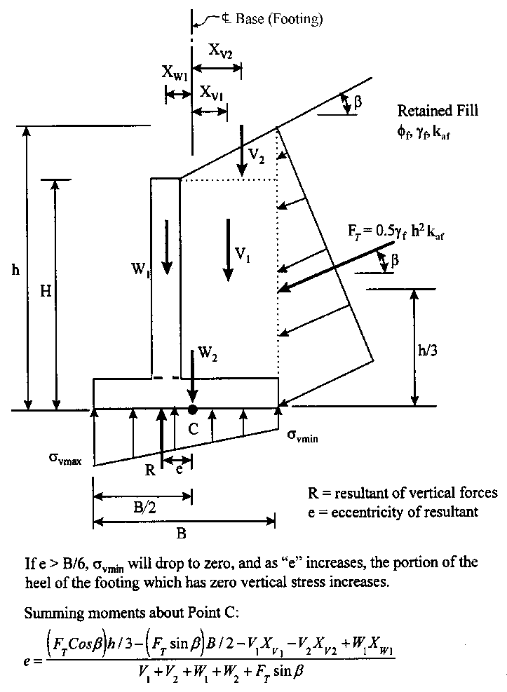 AASHTO LRFD Figure 11.6.3.2-2 Bearing Stress Criteria for Conventional Wall Foundation on Rock
🔖 Tips
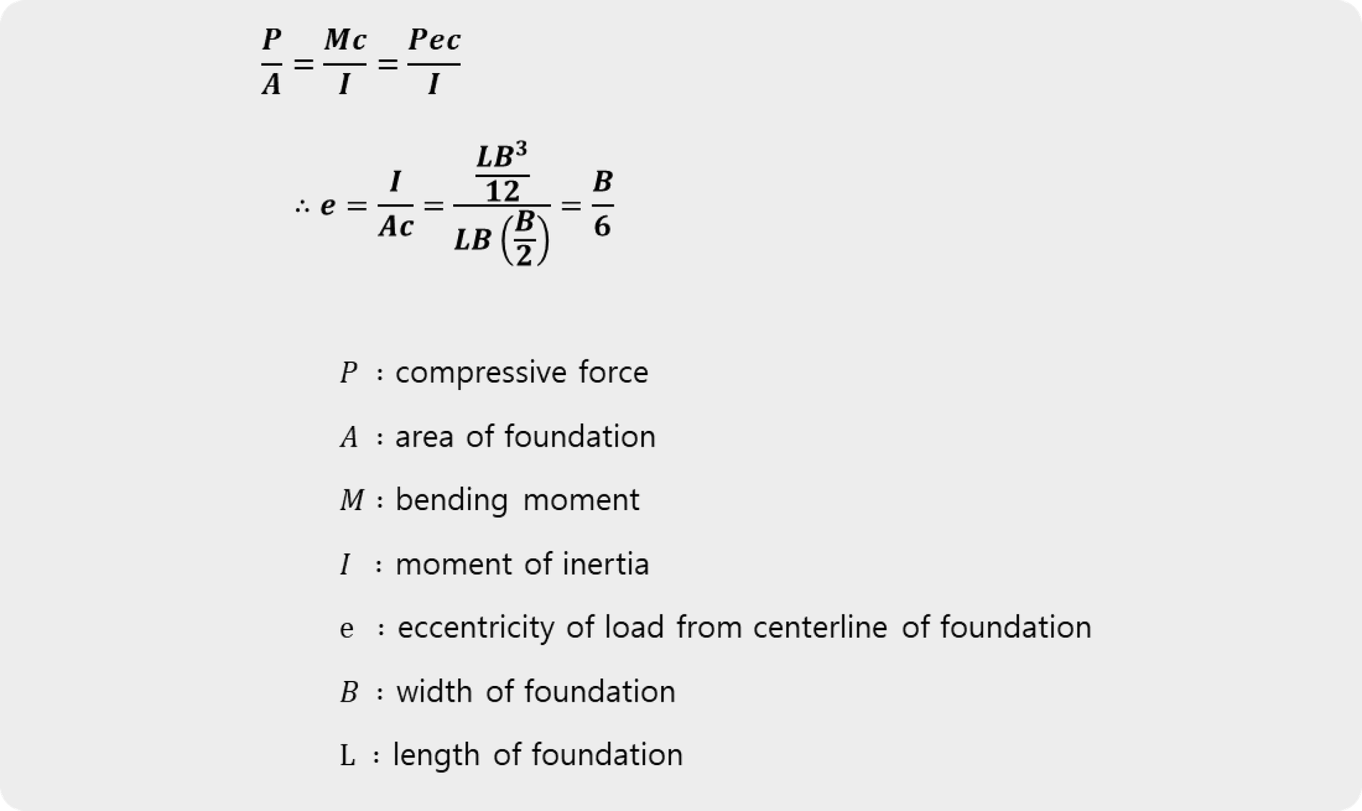
The standard for e is B/6 is related to the Kern Boundary. The vertical stress acting on the foundation can be calculated as the sum of the axial stress (P/A) and the bending stress (Mc/I).
When the axial stress and bending stress are equal, the eccentricity can be calculated, and the kern boundary is B/6 of a rectangular foundation.
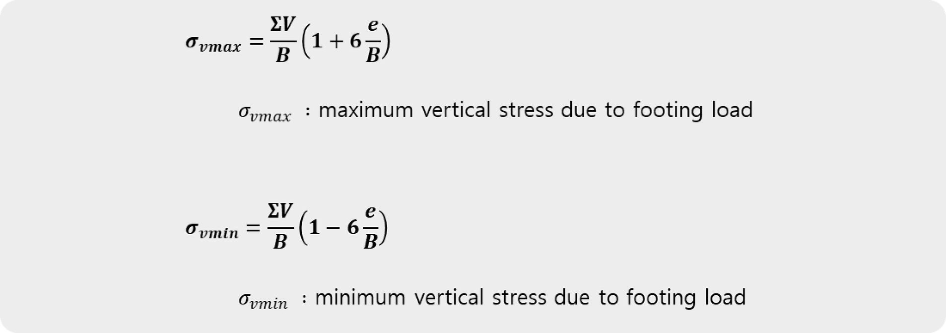
 The vertical stress
The eccentricity calculation
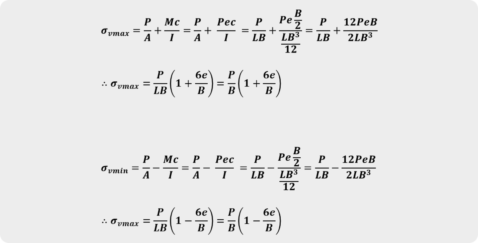
If the resultant is outside the middle one-third of the foundation. The vertical stress can be calculated as follows:
 The vertical stress calculation 2

The vertical stress calculation 3
🔖 Tips
When a structure is supported by rock, the vertical stress equation can be used to derive the following steps.
In this case, the length L of the structure is calculated in units of meters (1m).
 The resultant is within the middle one-third of the foundation
When e is greater than B/6, the vertical stress distribution becomes triangular. And the axial force acts at the centroid of the triangular stress distribution. In this case, the maximum vertical stress can be calculated as follows:
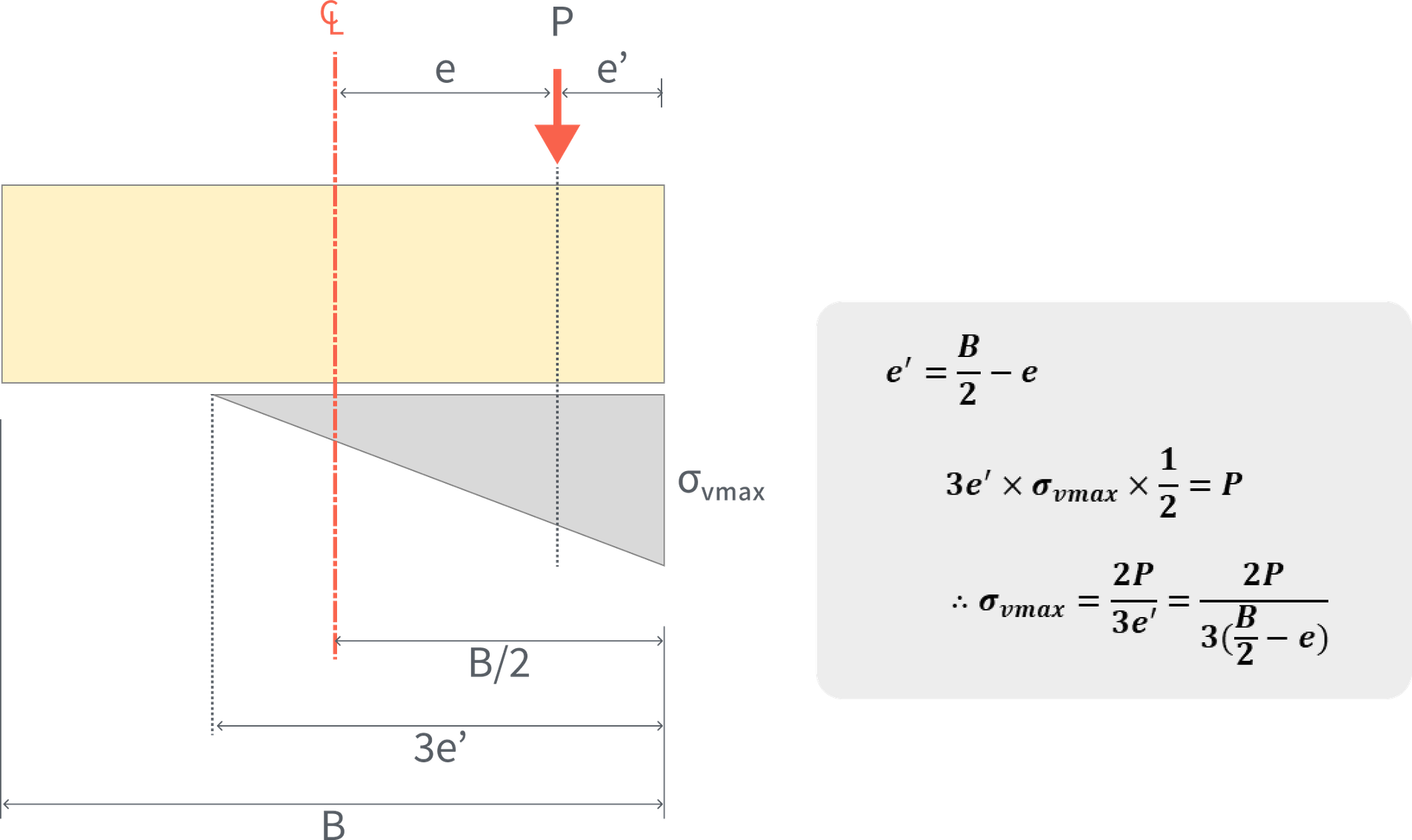
The resultant is outside the middle one-third of the foundation
B. Overturning (Eccentricity Limits)
The overturning of a structure is evaluated based on the overturning moment and the stabilizing moment calculated with the front of the footing toe (Point 'o'). The moment generated by the horizontal earth pressure results in the overturning moment that rotates the structure forward, while the self-weight of the structure and the weight of the backfill soil generate the stabilizing moment that rotates the structure backward.

You can check more of these details in the download file.