Get Started midas Civil
 Featured blog of this week

Development of anchor design
Currently, the design of anchors in the United States is being led by the ACI 318 Committee, with support from the ACI 349 Committee and the ACI 355 Committee, and ACI 318 Appendix D "Anchoring to Concrete" has been reorganized into Chapter 17 of ACI 318-14.
Until the late 1990s, ACI 318 and the AISC LRFD and ASD standards had no specific provisions for anchors in concrete. Appendix B of ACI 349-85 and the PCI Design Manual, Fifth Edition, provide basic design information for cast-in-place anchors. Historically, post-installed anchors' design has relied on data supplied by specific anchor manufacturers.
The 45-degree cone method, described in ACI 349-85 Appendix B and the PCI Design Handbook, 5th Edition, was created in the middle of the 1970s. In the 1980s, extensive experiments were conducted at the University of Stuttgart, Germany, on the performance of various anchors embedded in uncracked and cracked concrete with embedment depth, edge distance parameter, and effect of anchor group as independent variables.
The kappa method, introduced in ACI 349 and ACI 355 in the late 1980s, was also based on experiments conducted at the University of Stuttgart. In the mid-1990s, ACI 349 and ACI 355 compared the CCD(Concrete Capacity Design) and the 45-degree cone method. As a result, the CCD method was adopted.
This article presents the 45-degree cone and Concrete Capacity Design (CCD) method.
1. 45 - Degree Cone method
When deciding the design strength of an anchor, the lesser of the two strengths determine the design strength: 1. The strength of the anchor steel and 2. the strength related to the anchor's embedment characteristics should be considered. The strength of the anchor steel is related to the steel's properties and the anchor's specifications. The embedment characteristics of the anchor are also relevant to the anchor's strength; embedded length, concrete strength, interaction within the adjoined anchors, edge distance, and the type of anchor head.
In the 45-Degree Cone method, assuming the failure of the concrete is conical, as shown in the figure. The concrete stress resisting tensile force act in the anchor is calculated as follows.
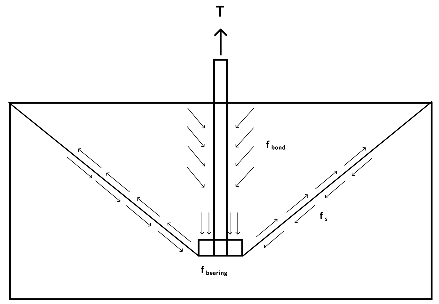
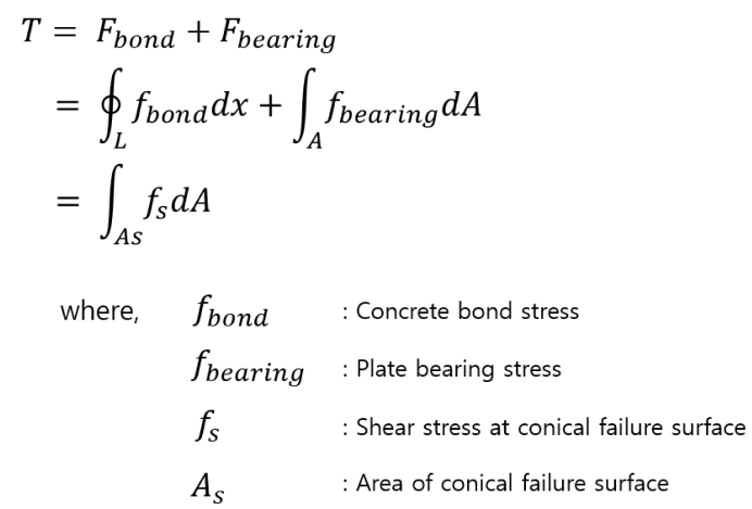
The forces on the anchor are divided into the adhesion force on the anchor surface and the bearing force on the end plate. The shear stress along the virtual fracture plane ultimately takes control in concrete fractures.
The shear stress can be separated into horizontal and vertical forces acting on the concrete's conical virtual fracture surface. The horizontal forces are offset due to the symmetrical nature of the anchor's left and right sides. The sum of the vertical stresses acting on the virtual fracture surface will eventually equal the sum of the tensile stresses acting on the horizontal projection of the virtual fracture surface. Therefore, the concrete failure strength can be calculated as the product of the horizontal projection area and the tensile strength of the concrete.
Before ACI 349-01 Appendix B was revised, the horizontal projected area was calculated by assuming a conical fracture shape at a 45-degree angle from the anchor head, as shown below. The concrete breakout strength calculated using this method is as follows.
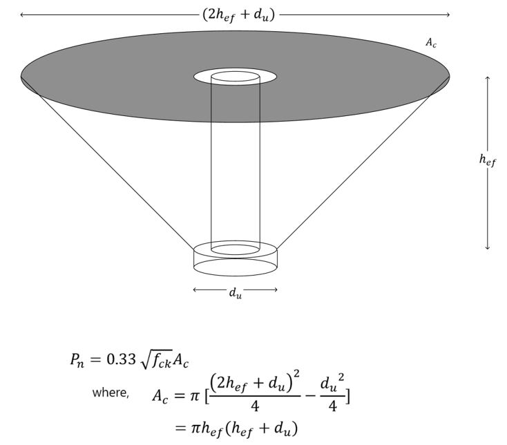
However, this method is based on a circular failure plane, complicating the strength calculation when installing multiple anchors. This method was determined unsafe through experiments in Europe and the U.S. when considerable strength is required. 1. Understimated strength at shallow embedded 2. Overestimated strength at deeply embedded.
.png?width=619&height=703&name=oncrete%20breakout%20load%20for%20cast-in-situ%20headed%20studs(Werner%20Fuchs%2c%201995).png)
2. CCD(Concrete Capacity Design) Method
To simplify the evaluation of anchor strength, ACI 349-01 and ACI 318-2 have adopted a CCD method based on fracture mechanics. The concrete breakout strength calculation is the difference between the CCD and the 45-degree cone methods. In the case of the 45-degree cone method, the fracture surface is assumed to be a cone with a 45-degree angle, so the strength calculation appears as the square of the embedment length as described above.
 Complete the form below to view the entire content.
.
.
.
CCD(Concrete Capacity Design) Method
Three failure mechanisms of group anchors consist of double-row arrangements.
- Case 1
- Case 2
- Case 3