Get Started midas Civil
 Featured blog of this week

Evaluating Tendons Through Simulation in Civil Engineering
As defined in General, Tendons refer to "steel wires, steel strands, or steel bars used for applying prestress to concrete structures." They play a pivotal role in introducing prestress to concrete members, compensating for concrete's material properties, which excel in compression but are weaker in tension.
Applying prestress to concrete structures involves either introducing compressive stresses by tensioning steel wires, tendons, or steel bars within the concrete or pre-bending steel reinforcement and releasing it under stress before concrete casting. The former method results in prestressed concrete (PSC) girders, while the latter yields Preflex girders.
In this content, we delve into simulating the installation of tendons in concrete beams using various dimensional elements (ie. 1D Frame, 2D Plate, 3D Solid included Tendon) and analyze how tendon stresses vary depending on the element type.
1. Overview
The evaluation of tendons typically entails utilizing finite element models for precise assessments of the impact of tendon placement and shape on concrete beam deformation and stress patterns. While various modeling methods are employed to represent tendons within concrete when creating finite element models, it is commonplace to model tendons within 1D beam elements.
However, for more accurate consideration of the structural behavior induced by tendon installation and to account for tendon placement and shape with greater precision, simulations can be conducted by embedding tendons within 2D plate elements or 3D solid elements.
In this content, we will compare the distribution of stress in tendons applied to midas Civil's 1D Frame elements with that in tendons applied to FEA NX's 2D Plate elements and 3D Solid elements, taking into account the dimensions of each applied element.
2. Modeling
The structural modeling, considering tendons, was categorized as follows and executed using midas Civil and FEA NX:
- 1D Frame Element with Tendon: midas Civil
- 2D Plate Element with Tendon: FEA NX
- 3D Solid Element with Tendon: FEA NX
The material and cross-sectional properties employed for this modeling are as follows:
- Concrete: C40
- Concrete Area: 0.5 x 0.5 m
- Tendon: SWPC7B
- Tendon Area: 2,635.3 mm²
- Duct Diameter: 100 mm
- Relaxation Coefficient: CEP-FIP 5%
- Tendon Ultimate Strength: 1,863.26 MPa
- Tendon Yield Strength: 1,569.06 MPa
- Curvature Friction Factor: 0.3
- Wobble Friction Factor: 6.6E-06 1/mm
- Anchorage Slip: Begin & End 0.6 mm
The characteristics of the tendons applied to midas Civil and FEA NX are as follows (Figures 1 & 2). These characteristics were considered when assuming the curvature of tendons:
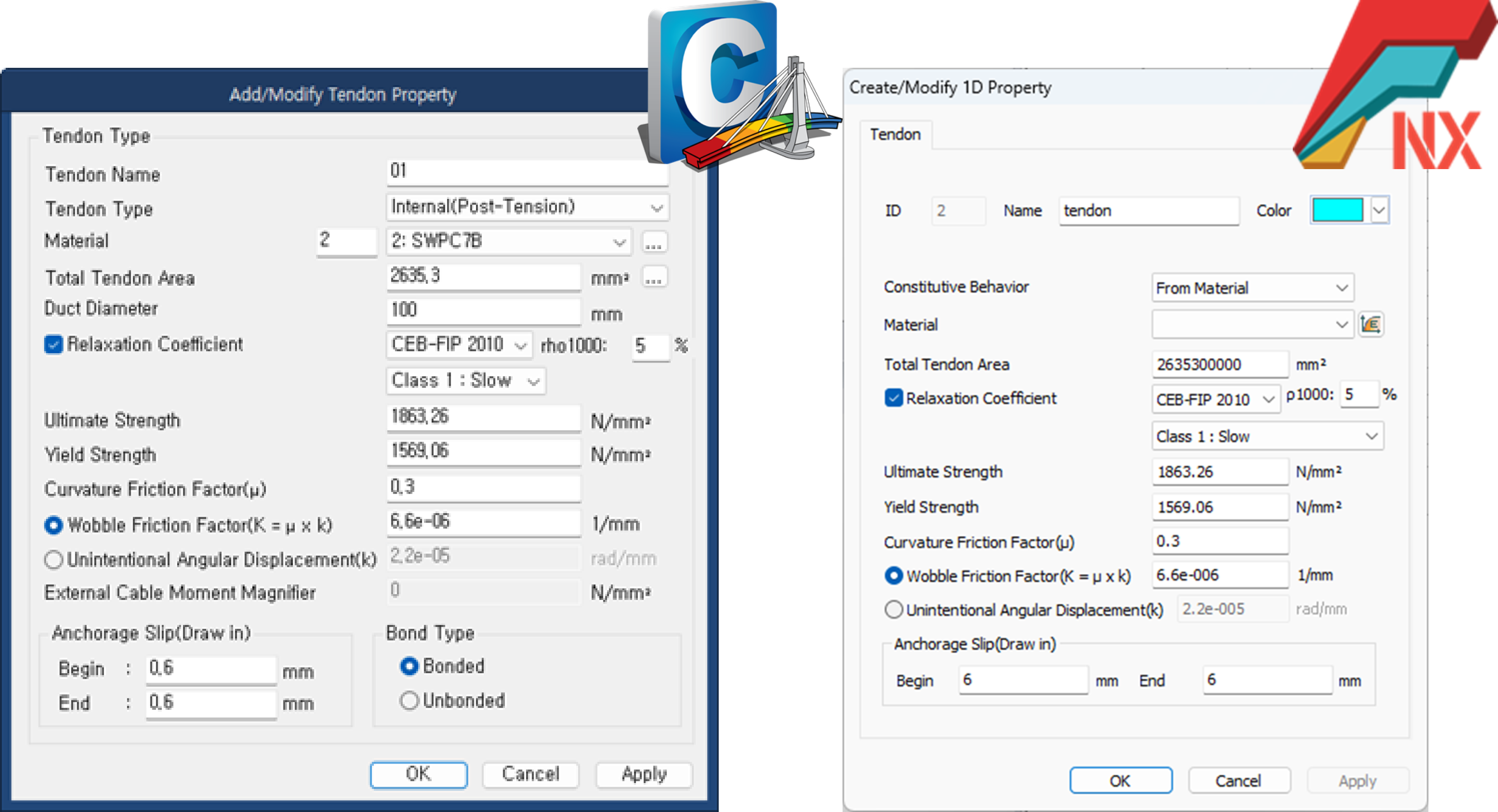
<Figure 1. Tendon Property>
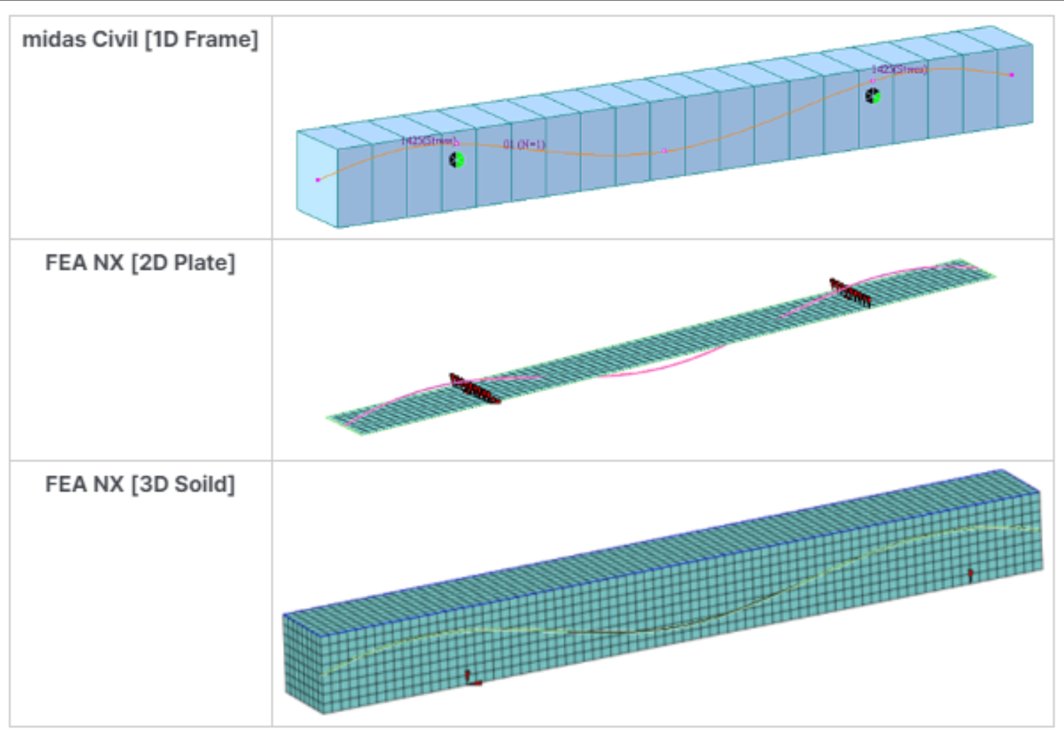 <Figure 2. Tendon Analysis Modeling>
Using the models configured as shown in Figure 2, we applied tension to the tendon ends and compared the stress patterns in the tendon and the structure for each applied element.
3. Simulation Results
The stress in tendons for each element type was calculated as shown in Figure 3, and it was observed that there was minimal difference in tendon stress depending on the element's dimension. However, assuming a curvature configuration, modeling tendon shapes more accurately showed a trend of producing slightly higher stresses in 1D Frame elements.
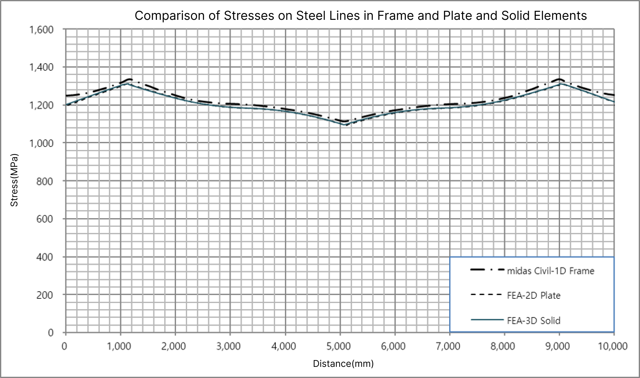 <Figure 3. Comparison of Tendon Stresses by Element Type>
When comparing 2D Plate elements to 1D Frame elements based on different element dimensions, the stress in tendons showed a maximum difference of 1.90%, and in the case of Solid elements, a maximum difference of 1.86% was noted. The detailed result for tendon stress is shown below in Table 1.
| Category |
Stress(MPa) |
Compared to Frame(%) |
Remarks |
|
|
Frame |
Max |
1,336.17 |
- |
|
|
Min |
1,113.82 |
- |
|
|
|
Plate |
Max |
1,312.00 |
1.84 |
|
|
Min |
1,093.00 |
1.90 |
|
|
| Solid |
Max |
1,312.45 |
1.81 |
|
|
Min |
1,093.47 |
1.86 |
|
|
<Table 1. Comparison of Tendon Stresses by Element Type>
The structural stresses induced by tendon forces were calculated as shown in the figure below. The stresses in the structure exhibited a similar trend across all element dimensions.
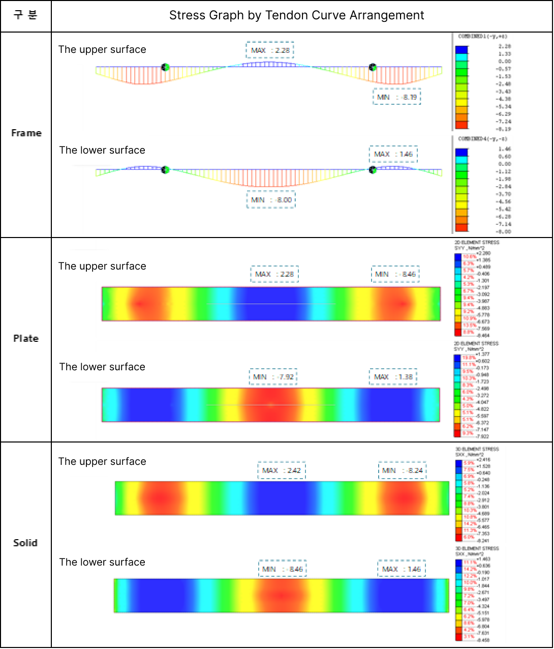 <Figure 4. Comparison of Structural Stresses by Element Type>
Depending on the dimension of each element, when comparing the results of applying 2D Plate elements to 1D Frame elements, the structural stresses in the structure showed a maximum difference of 5.80%. In the case of 3D Solid elements, the maximum difference reached 6.38%. The detailed result for structural stress is shown below in Table 2.
|
Category |
Stress(MPa) |
Compared to Frame(%) |
Remarks |
||
|
Frame |
Top |
Max |
2.28 |
- |
|
|
Min |
-8.19 |
- |
|
||
|
Bottom |
Max |
1.46 |
- |
|
|
|
Min |
-8.00 |
- |
|
||
|
Plate |
Top |
Max |
2.28 |
0.00 |
|
|
Min |
-8.46 |
3.19 |
|
||
|
Bottom |
Max |
1.38 |
5.80 |
|
|
|
Min |
-7.92 |
1.01 |
|
||
|
Solid |
Top |
Max |
2.42 |
5.79 |
|
|
Min |
-8.24 |
0.61 |
|
||
| Bottom |
Max |
1.46 |
0.00 |
|
|
|
Min |
-8.46 |
6.38 |
|
||
<Table 2. Comparison of Structural Stresses by Element Type>
4. Conclusion
The simulation of tendons can be conducted using various element types, and the choice of element dimension should align with the engineer's needs and judgment.
In this content, we demonstrated how the choice of element dimension can affect tendon application, showing that the difference remains within approximately 10%. However, it's important to note that this difference can be more significant or less significant depending on how precisely the curvature configuration of tendons is modeled.
Today's content aimed to shed light on the differences in tendon application based on element dimensions. The simulations indicate that these differences remain minimal, staying within approximately 10%. Tendon simulation can now offer engineers more diverse options, allowing for a broader range of simulations using midas Civil and FEA NX, depending on their needs.